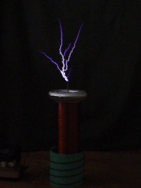
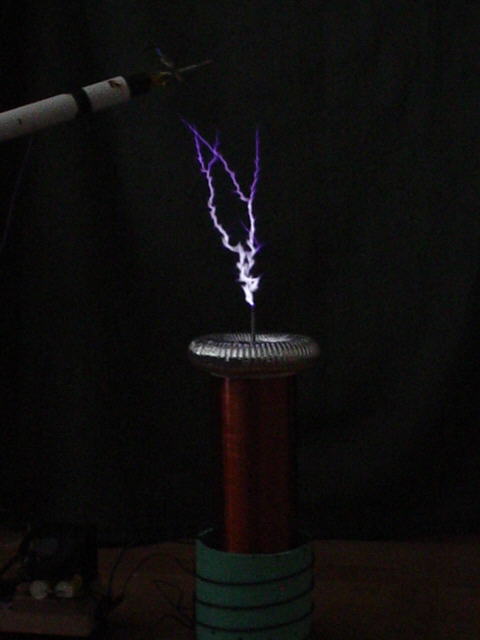
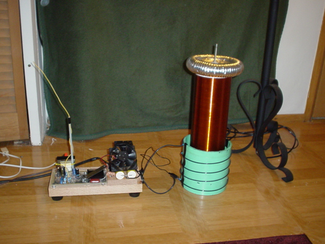
SSTC 1
This was my very first SSTC, constructed in May of 2003. It was built with much help from Justin Hays from hvguy.com, many thanks go to him for his time and help. Some say that I was lucky for this SSTC to work so well for my first time and I would agree. It was based off of Justin's design, I believe that is part of the reason it worked so well.
SPECS FOR THIS COIL:
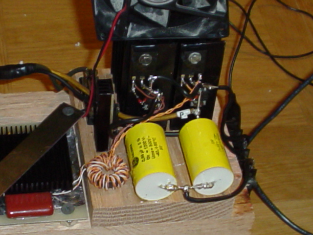
Driver electronics: A 555 timer generates 'start up' waveforms to get the whole circuit oscillating. The antenna senses the output polarity of the secondary coil and sends this to a comparator (MAX913). The MAX913 then generates a beautiful square wave from the antennas signal. A 74HC14 hex schmitt-triggered gate is used to boost the signal from the 913 to a higher current, and also give noise immunity. A full bridge of gate driver chips (2x MAX4420 and 2x MAX4429) drive a ferrite core with a 14 turn primary and 2 x 18 turn secondary windings, this in turn drives the power MOSFETs. Finally a half bridge of IRFP260 MOSFETs switch half-wave rectified mains into the primary coil. The IRFP260s are rated at 200v and 46A. I run the coil at 140V, so each fet gets 200v peak, not much room for voltage spikes, but it does work reliably.
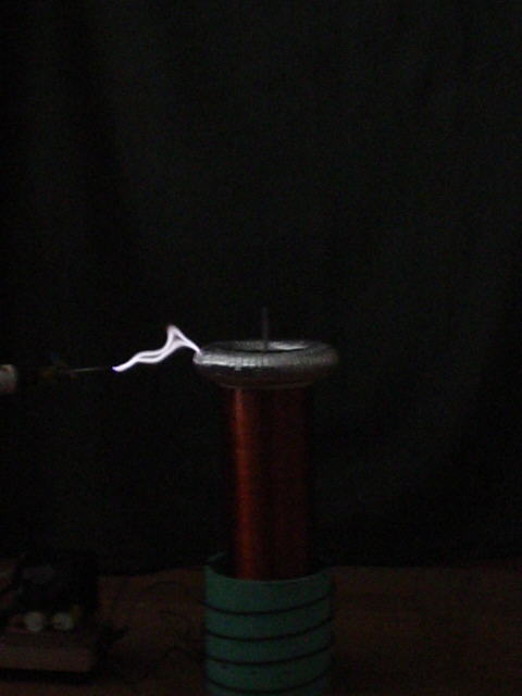
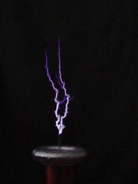
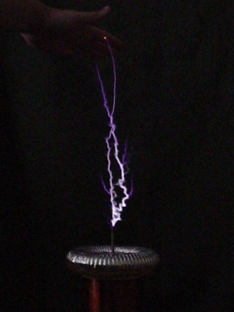
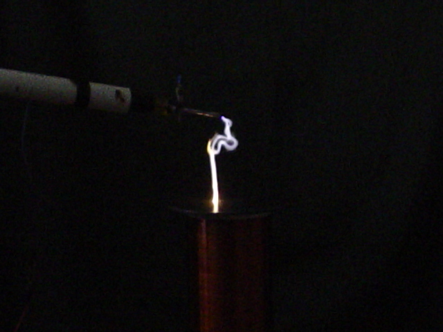
Secondary: 4.5"x 14" of 30awg wire. Small toroid of 7"x1.25". A breakout point is needed.
Primary is 4 turns of 12awg on a 6.3"PVC form. The coil is space wound to span 6" length with only 4 turns.
Spark length is 14" at less than 1000W input power.
CONSTRUCTION DETAILS:
Within this page I will give the schematics for my first SSTC. The schematics are basically the same as from hvguy.com, so credit MUST be given to them. I will give special notes for each schematic as needed.
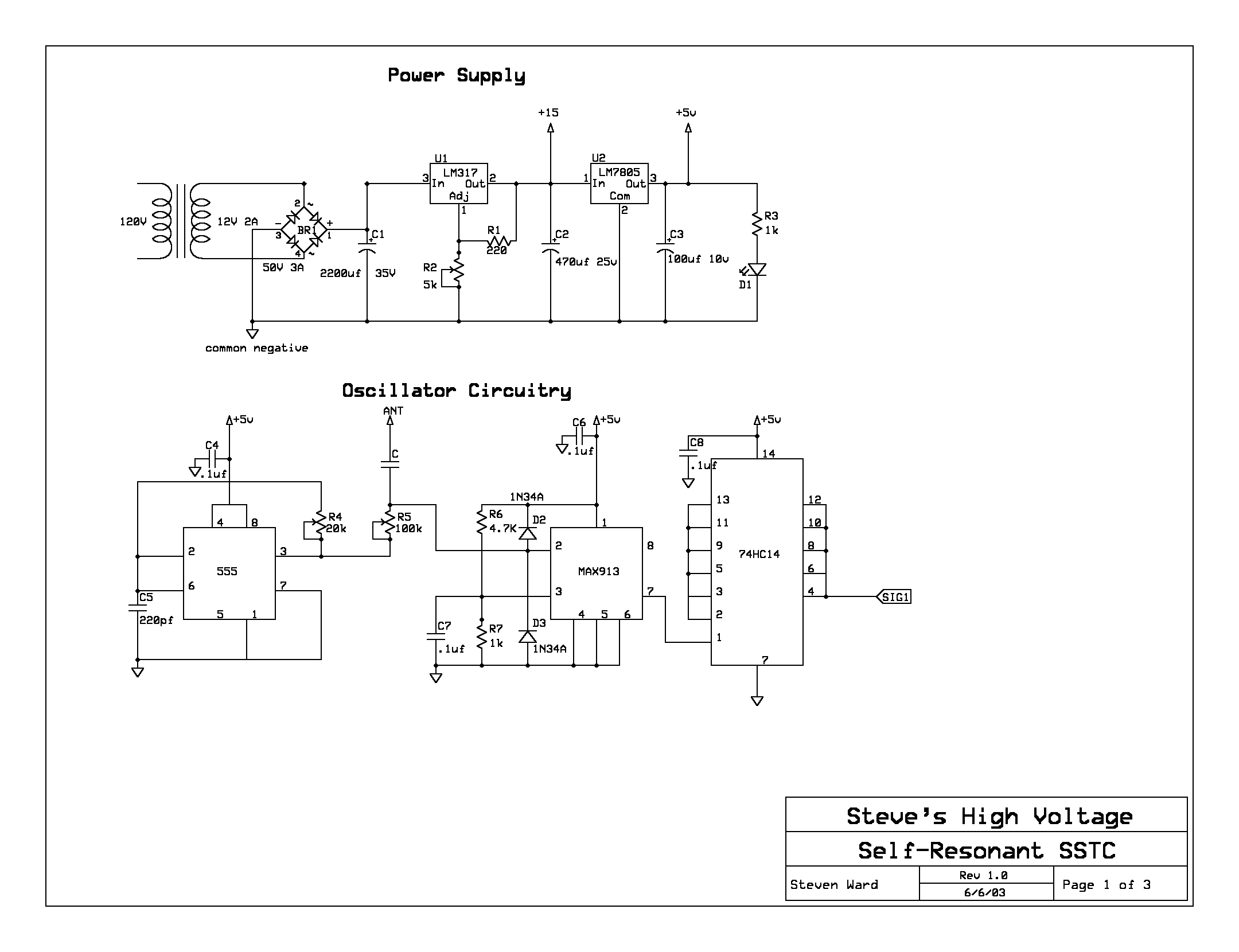
POWER SUPPLY AND OSCILLATOR CIRCUITRY
The circuit board was made using a double sided board. The top layer was left as one large plane and made the negative for the circuit. This improves shielding from RF greatly, and it helps when designing. Set R4 for a frequency that is close to the TCs Fres. Then Set R5 to 0 in order to do phase testing for the gate driver. When phasing is correct, R5 will need to be set to some several 10k. Set it with the variac at about 3V input to the bridge and find the value that allows it to oscillate with the signal from the antenna. Mine will start up with the variac set at about 2%. Find the best setting before turning up the power! This is critical. The 1N34As are critical. 1N60s are a perfect substitute. I get mine from http://www.allcorp.com/
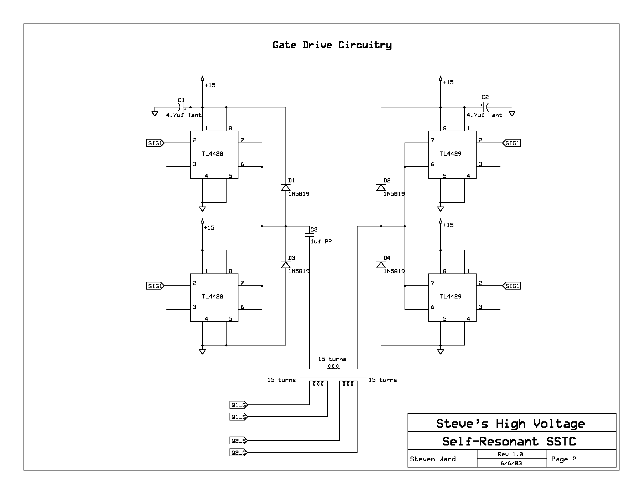
GATE DRIVE CIRCUITRY
All 4 of the gate driver chips need heat sinking. hvguy.com says
to mount them in a small area and find a way to clamp a CPU heatsink onto
them. That is what I did. Without the heatsink, the chips run HOT! You can
use either the MAX or TC versions of the chips, I don't notice any difference
between the 2. The TC version is less expensive :o). The transformer needs
to be a ferrite core. The best cores are found inside of line filters or on
monitor cables. I also found square ferrite transformers in an old monitor.
I removed the windings and put my own on using 26 awg wire. If the transformer
does not produce very square waves, its not the right material. look further.
You can buy proper toroids from http://www.cwsbytemark.com/ham.php The exact
core I just bought (tested by hvguy.com) is F-114A-77 for $2.45 each. There
are also some smaller ones, just look for the type 77 material, its one of
the best for this use. With these larger cores you could probably drive at
least 4 gates of smaller fets (IRFP260,460,740 etc). If
I find any other suppliers of ferrite cores, I will list them here and possibly
elsewhere on my site. UPDATE: I found that the cores sold here
http://www.goldmine-elec.com/
are good as well. You want the "Medium Ferrite Core (Toroid) - G6683
$1.00". You actually get 5 toroids for $1!!! They give very clean square
waves (just as well as the F-114A-77 cores), but may or may not be able to
drive a full bridge of larger MOSFETs. Chances are they can. But at $.20
each, you may as well stock up and use many of them.
HALF BRIDGE AND START UP CIRCUITRY
The MOSFETs were chosen for the fact that I only have a 120V line and they were on ebay. They will handle lots of current. They need a good sized heatsink. The MUR1560 diodes are just ultra fast 600V 15A diodes. I'm sure there are many substitutes. The 15V zeners should be rated 1W or better. Make sure that the gate drive signals are out of phase with each other so that the MOSFETs turn on alternately. The 10 ohm resistor is to reduce oscillations that will appear at the switching transitions of the gate. They smooth everything out nicely. Don't allow the gates to see more than 40v(p-p). They should get at least 20V. I use about 30V. To clear it up, the gates should get + 10V (minimum) and then - 10V. No more than +20V should be seen across the gate and source.
The start up circuit is nothing more than a voltage divider on the 120v line to provide 12V to an RC on the gate of an additional MOSFET. This causes the gate to charge up over several 60hz half-cycles, allowing for a smooth turn on transition.
Schematics