Class-E SSTC
Created 5/13/05
I started messing around with my Micro SSTC a few days ago and decided it was time to improve it. After seeing Richie's 4mhz SSTC and reading about Class-E operation, I decided it was time to employ this with the little SSTC. In fact, without actually realizing it, the Micro SSTC was already close to operating class E... the 2.2nF capacitor across the MOSFET was just too small for optimum performance. One other thing I wanted was longer sparks. Interrupting the drive signal helped make longer sparks, and increasing the supply voltage helped even more. The circuit below is the result of my efforts:
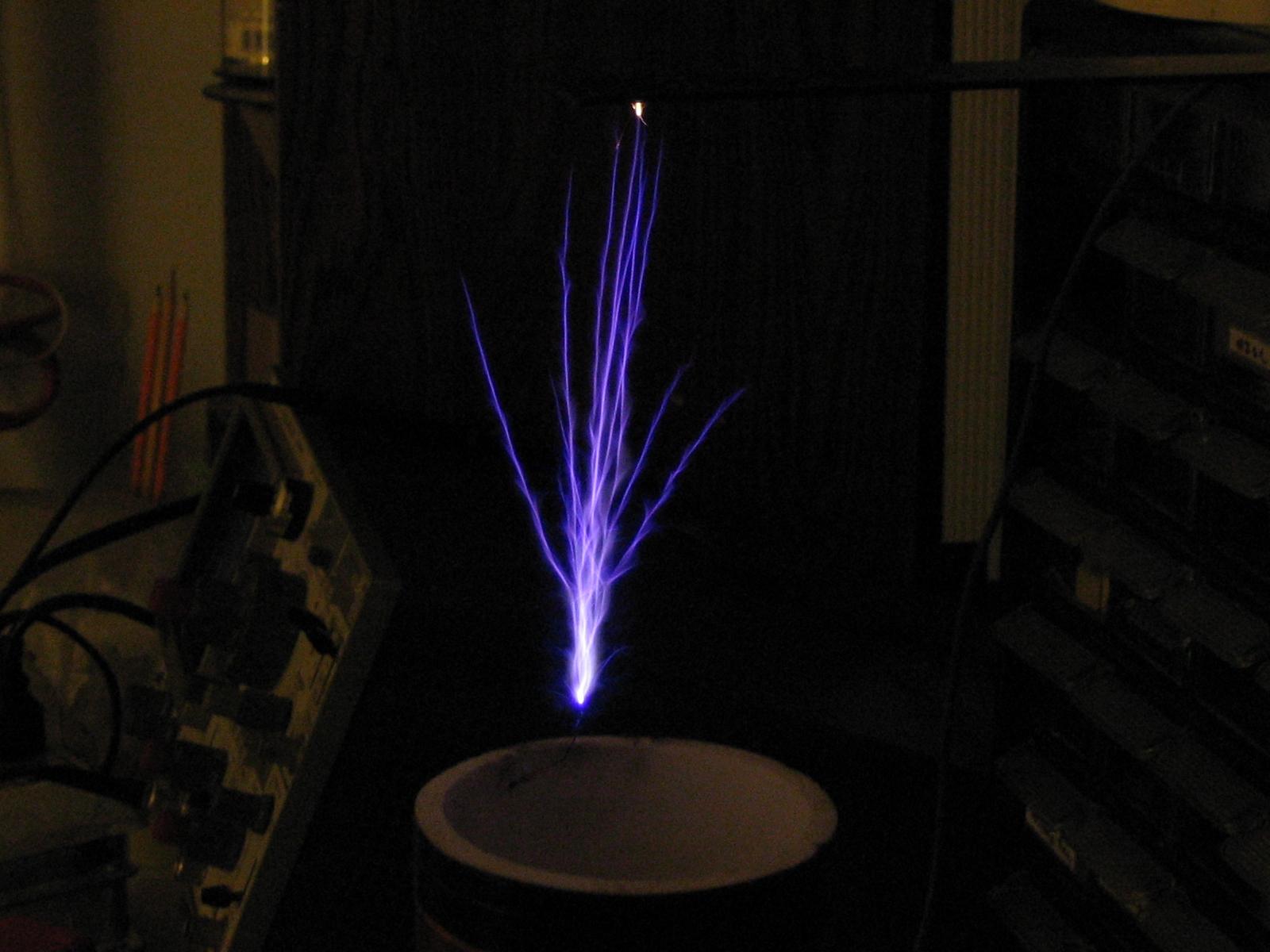
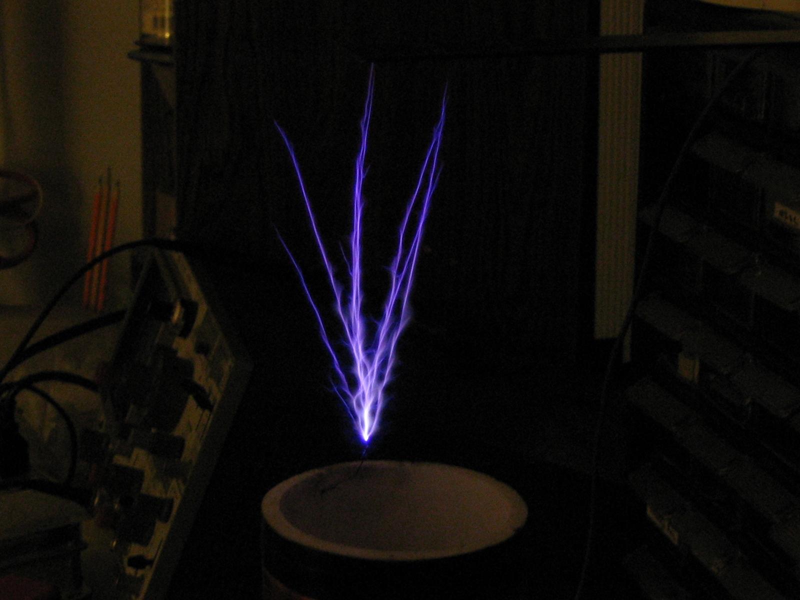
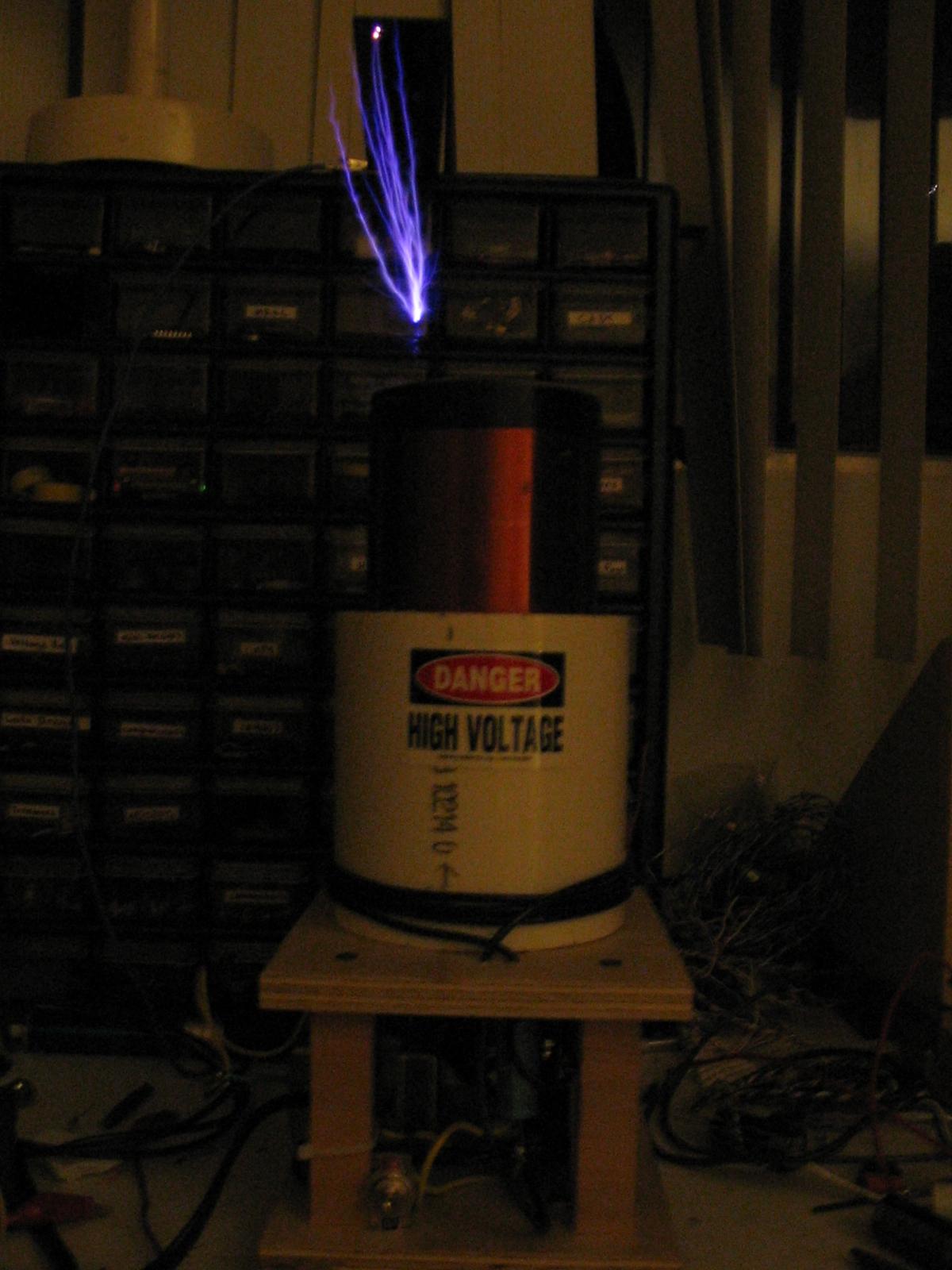
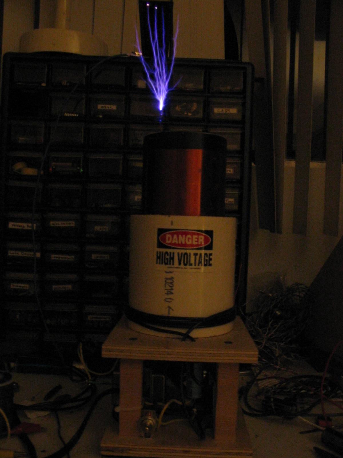
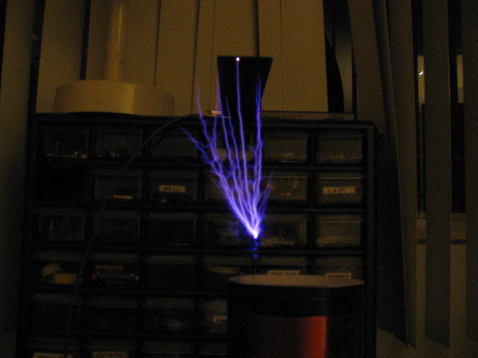
And some 5" sparks:
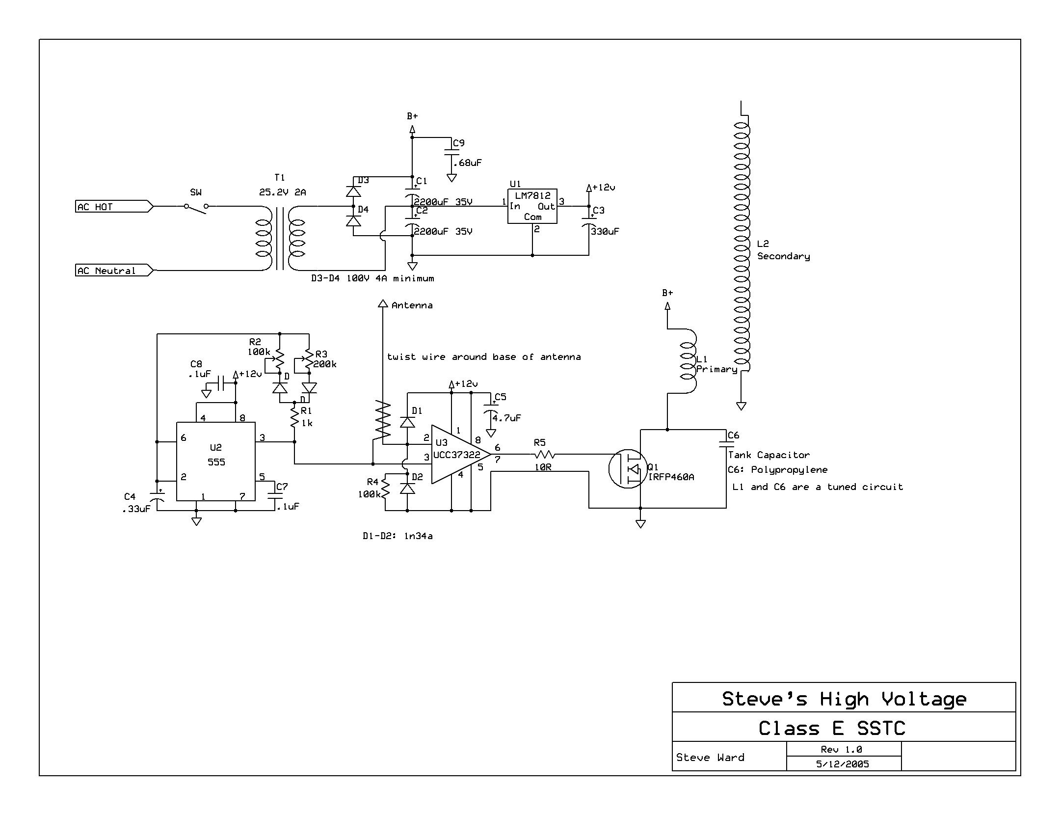
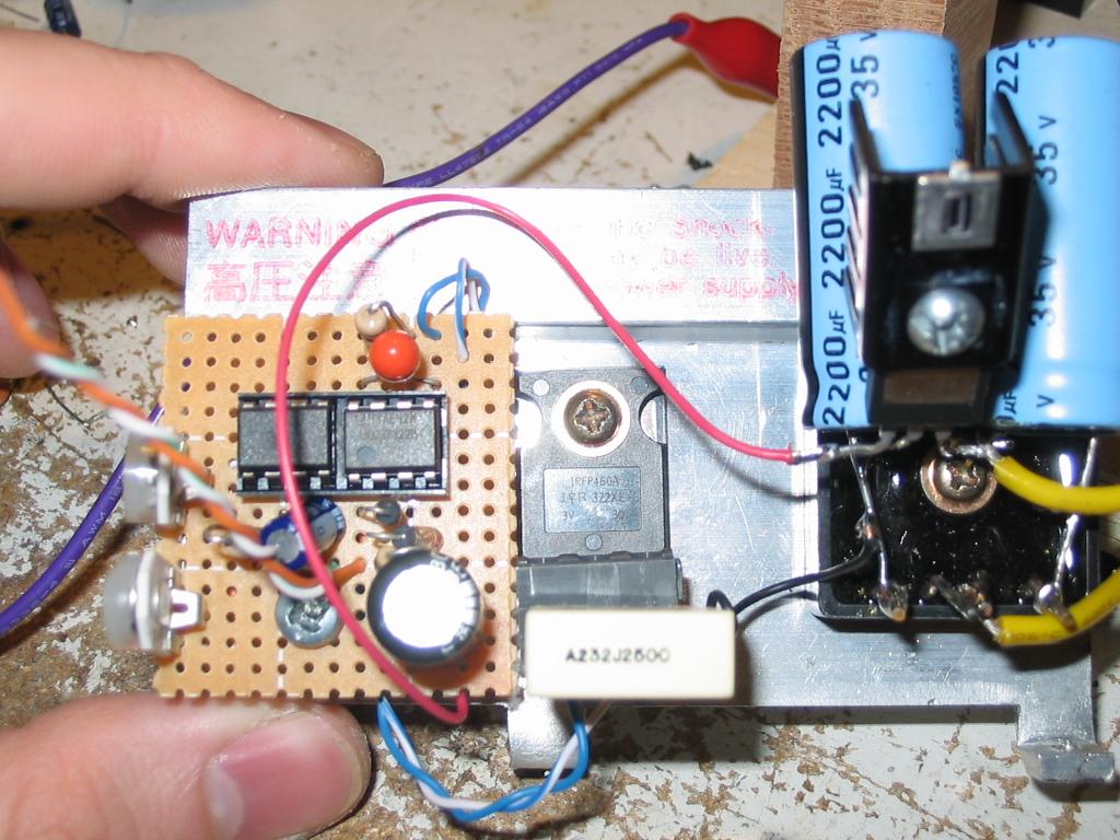
The driver:
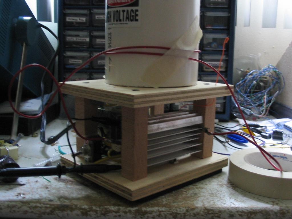
The whole coil (primary doesnt reflect current configuration):

Notice the voltage doubler for up to 70VDC. The 555 is operating at a PRF of about 30hz in normal operation to keep power demand low on the small 50W transformer. The output of the 555 is tied directly to the ENABLE input on the gate driver. One important detail is that a lead attached to the output of the 555 twists around the base of the antenna. This acts as a capacitor, and when the 555 shoots high, a small voltage spike is coupled through this capacitance into the antenna. This small pulse starts the oscillations! After that, the antenna senses the E-field around the secondary. Since the base of the antenna is clamped with diodes, the voltage seen at the base of the antenna is actually shifted 90 degrees, making it in phase with the secondary base current.
L1 and C6 make up a tuned circuit of sorts. Basically what happens is when the MOSFET turns on, current builds up in the primary coil and any other leakage inductance in the circuit. When the MOSFET opens up, the stored energy is released as the magnetic field collapses. This generates an EMF which charges the capacitor across the MOSFET. Once the capacitor has reached its maximum voltage, it begins driving voltage back through the primary inductance (voltage falls). Our hope is that after the voltage peaks, it returns back to zero smoothly (meaning the circuit is critically damped). This means that there is no turn on switching loss since the voltage across the MOSFET is zero when it turns on, and if the voltage doesn't dive lower than zero, there is no current flow in the reverse diode. The below waveforms are from a simulation of my circuit, they should help explain the operation a little. Note, the Red trace is the secondary voltage (Scaled by 1/1000), the blue trace is the voltage across the tank capacitor (scaled down by 1:10), and the green is the signal applied to the MOSFET gate driver.
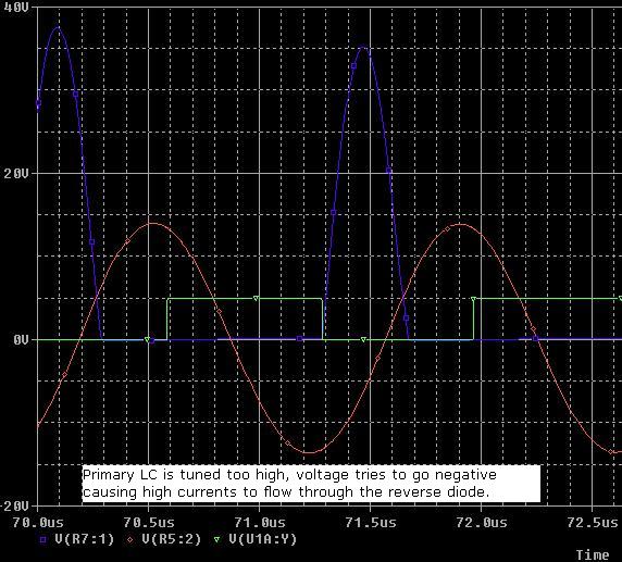
CASE 1: In this trace shot, the primary LC is tuned too high for proper class E operation. The tank voltage (blue) dives down to zero as the circuit is under damped. The voltage would normally swing negative, but there is a diode across the MOSFET blocking any reverse voltages. This diode goes into forward conduction, wasting power. Also notice that the voltage peaks much higher than it normally should (200V is normal, but its peaking to 350V here!) under this condition, because the capacitors storage energy is too small compared to the energy stored in the inductor.
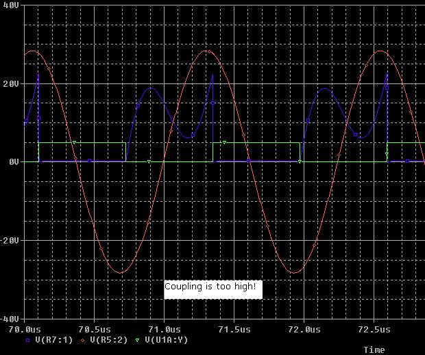
CASE 2: This illustrates how critical coupling can be. In this simulation, the primary LC is set properly, but the coupling is too high. This means that the energy gets sucked up too fast by the secondary streamer. The voltage waveform is over damped in this case and does not touch back down to 0V. The MOSFET must then switch ON with a high charge on the miller capacitance, causing some switching losses.
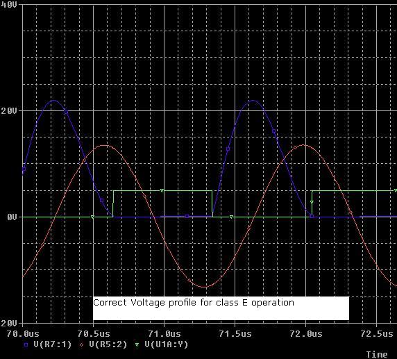
CASE 3: This waveform is the ideal profile for the voltage across the capacitor. The voltage *just* hits zero when the MOSFET turns back on, this means the circuit is critically damped. This means there is almost no charge in the miller capacitance, and the reverse diode is not conducting (at least not any appreciable current). This should give the highest efficiency, and is true class E operation.
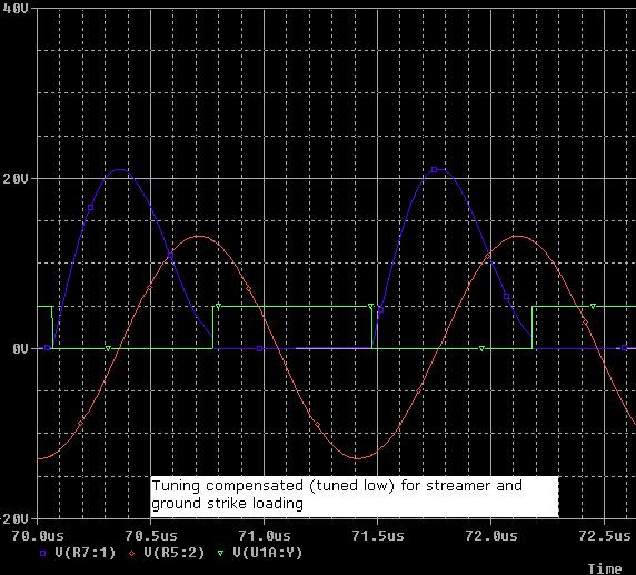
CASE 4: This final waveform is how I actually tune the circuit. The primary LC is tuned slightly lower than optimal (that is, slightly under damped), so that there is about 20V or so across the MOSFET when it turns back on. The reason for this is that longer streamers, nearby objects, or allowing the streamers to strike a grounded target will detune the coil. When this happens, the voltage profile actually matches the ideal case above.
Here is a scope shot of the MOSFET D-S voltage in operation, 50V/div:
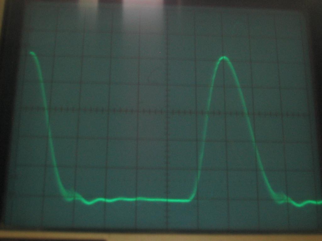
I had to use a 10nF shunt capacitor, with a 1.2 turn primary with extra leakage inductance on the side. This was the result of lots of experimentation.