CCPS Design
UPDATED : 10/27/06
Within this page I plan to show how our CCPS design came to be
so that others might learn from this experience. A good portion of the
work done on this project was also done by Sean Taylor.
Our Goals: The original idea was "wouldn't it be
cool to replace a pole pig with a little 50lb inverter/transformer power
supply?". Of course the answer is YES!! The plan was originally to
use 2 of the largest ferrite U cores available, running at 3kva each for a 6kva
power supply. A charging voltage of 15kv sounded good enough and should be
possible to make a transformer for that voltage. This would work out to
about 500-600mA RMS output from the transformer at ~11kV RMS output voltage.
Our early attempts: The first thing we did was "try
something". We needed to get a hands-on understanding of what we were
dealing with there. From previous experience I realized that insulating
50khz AC is *not* easy. So we wound a few coils, most of them containing 3
layers of winding of 24-26awg magnet wire, typically about 250 turns on the
secondary. Our primary winding was just 10 turns of 12 awg THHN. We
ran the transformer directly off of my basic inverter design (full-bridge of
IGBTs outputting a solid square wave voltage drive). The problem here is
that transformers are almost purely inductive. This gives a nice
triangular current waveform, where of course the switching transitions occur
when the current is at its maximum! We suffered huge switching losses and
blasted a handful of IGBTs before I said that we really should be using a
resonant load topology to ease switching losses. Here are some pictures
from our earlier work:
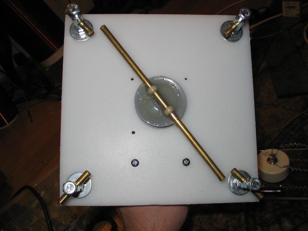
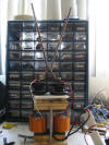
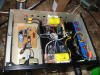
 The
trusty H-bridge. Notice we used quick connects for the IGBT connections.
This was what we came up with after getting sick of unsoldering the IGBTs from
the board after each failure. Now IGBT replacement is quick (and slightly
less painful).
The
trusty H-bridge. Notice we used quick connects for the IGBT connections.
This was what we came up with after getting sick of unsoldering the IGBTs from
the board after each failure. Now IGBT replacement is quick (and slightly
less painful).
 Here
are 2 secondaries we wound. Both were attempts at vacuum potting (which
actually seemed to work fairly well, despite the rather thick epoxy we used).
Both coils were 3 layers of 24awg winding, about 250 turns on each coil.
Each coil should have been producing about 10kv peak, so 20kv peak for the 2
windings or about 14.1kv RMS.
Here
are 2 secondaries we wound. Both were attempts at vacuum potting (which
actually seemed to work fairly well, despite the rather thick epoxy we used).
Both coils were 3 layers of 24awg winding, about 250 turns on each coil.
Each coil should have been producing about 10kv peak, so 20kv peak for the 2
windings or about 14.1kv RMS.
 Here
is one of the best arcs we ever produced from this transformer. Lots of
current, but very little short circuit voltage. Soon after this arc, the
inverter dies again. I've had it with this! At about this time I
began researching the SLR (series load resonant) topology.
Here
is one of the best arcs we ever produced from this transformer. Lots of
current, but very little short circuit voltage. Soon after this arc, the
inverter dies again. I've had it with this! At about this time I
began researching the SLR (series load resonant) topology.
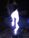
 These
are flames left over just after an arc extinguished (yes, the arc is HOT).
These
are flames left over just after an arc extinguished (yes, the arc is HOT).
The SLR topology: Nearly all of my research on this
topology came from Marco
Denicolai's website, extra thanks to him! But despite his great
explanation, I will continue to summarize the operation of this topology.
Basically, we employ a series capacitor with the transformer
primary to resonate with the leakage inductance of the primary winding.
The resonant frequency is given by:
Fo=1/(2*pi*sqrt(L*C))
I have found that a Fo between 100-200khz seems to work well.
Now, we use what is called the "surge impedance" to determine
the current that will be developed at a given voltage for an LC circuit.
Its important to note that the surge impedance only describes the current during
1 half-cycle of operation. This topology does not allow for "resonant
rise" effects, so we only concern ourselves with half-cycle increments of
operation.
Z=sqrt(L/C)
Then using Ohms law:
V/Z=I
we find the peak current that will be present in the primary
circuit.
I found that I had to add an inductor in series with my
transformer, simply because the leakage inductance of the transformer was simply
too low to achieve the proper balance between operating frequency and primary
current.
Now, the IGBT drive timing is very crucial to proper operation
of this topology. The drive is actually running with 50% deadtime as the
waveform below will show:
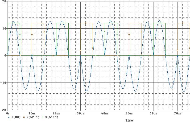
In blue is the primary current. The green and orange are
the IGBT drive signals. Notice how the green IGBT turns on, and the
current evolves as a sine wave and swings to zero (5uS) and in fact swings
negatively to nearly the same amplitude. Since the slope of a sine wave is
relatively slow, there is some margin for error for the IGBT to turn off
within a specified time. Also, the switching speed does not need to be
quite so fast, because the current is near zero when switching, so switching
losses are reduced considerably. Now at 10uS the opposing set of IGBTs
switch ON and *reverse the flow of current in the LC circuit*. Again we
have the same current waveform, just in the opposing direction. One full
"cycle" of operation is 20uS in length. We can see that the drive is
operating at 50khz while the primary LC is tuned to exactly twice that
frequency, at 100khz.
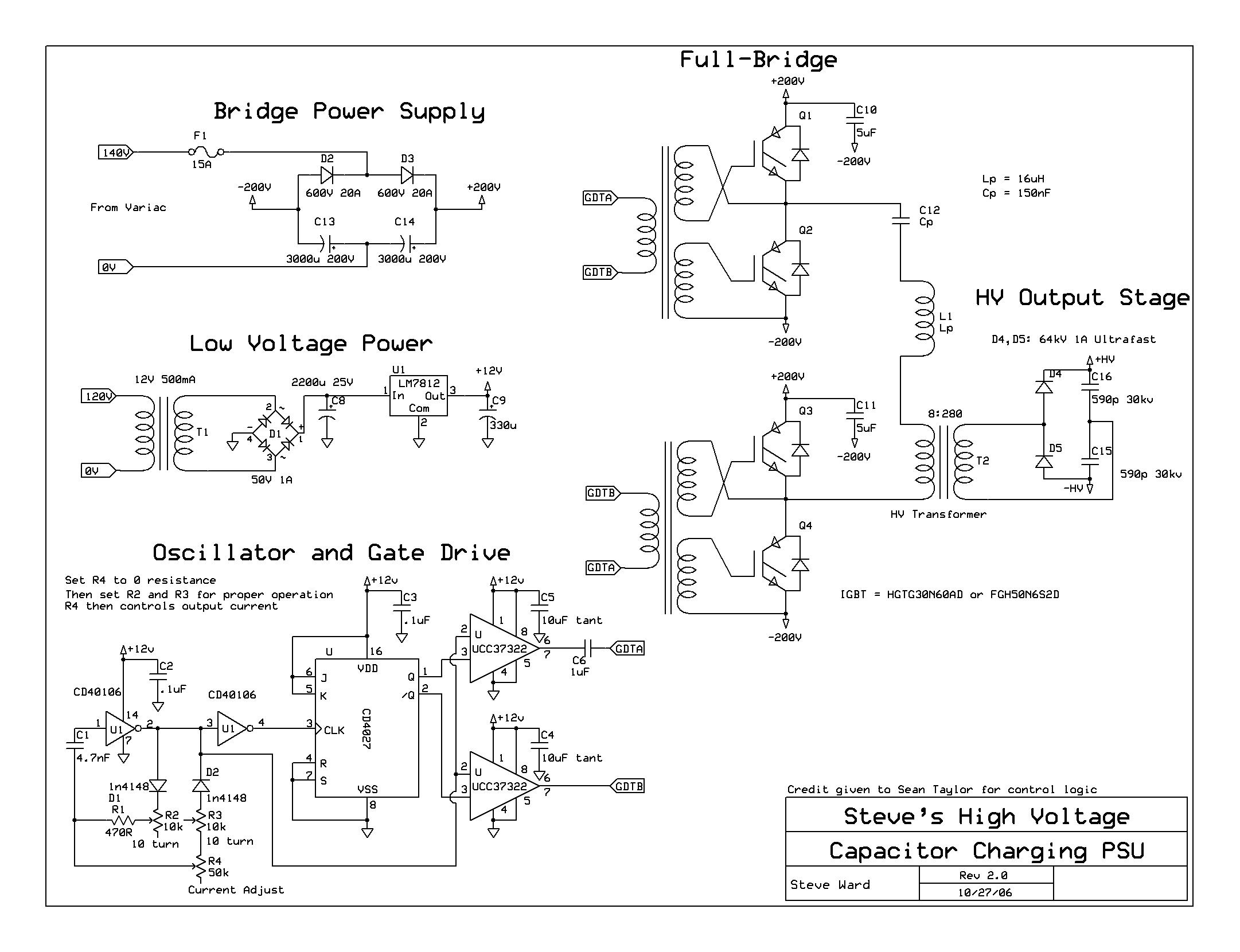
Schematic: Revision 1
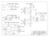
Schematic: Revision 2 (employs variable current control)

More Recent Work: Not only did I begin to employ the SLR
topology, but I redesigned the transformer itself:
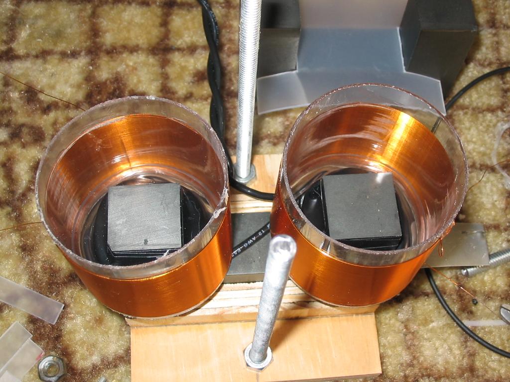
 Seen
here are 2 single layer secondaries wound with 30awg magnet wire. This
yields nearly 280 turns for the 2 windings combined. The output is now
12kv RMS, center tap grounded.
Seen
here are 2 single layer secondaries wound with 30awg magnet wire. This
yields nearly 280 turns for the 2 windings combined. The output is now
12kv RMS, center tap grounded.
 Here
we can almost see the primary windings. They are inside the secondary
windings near the low end of the winding (which is grounded). The primary
consists of 8 turns of 12awg THHN, this is for 400VDC full-bridge drive at 70khz
inverter operation (LC is tuned to 140khz).
Here
we can almost see the primary windings. They are inside the secondary
windings near the low end of the winding (which is grounded). The primary
consists of 8 turns of 12awg THHN, this is for 400VDC full-bridge drive at 70khz
inverter operation (LC is tuned to 140khz).
 And
of course it works! Here it was producing nearly 700mA RMS on the
secondary side!
And
of course it works! Here it was producing nearly 700mA RMS on the
secondary side!
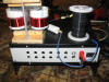
 The
driver has been installed into a nice aluminum box. This driver should be
fine at 3kva, and might work as well at 6kva, but that has yet to be seen.
The
driver has been installed into a nice aluminum box. This driver should be
fine at 3kva, and might work as well at 6kva, but that has yet to be seen.
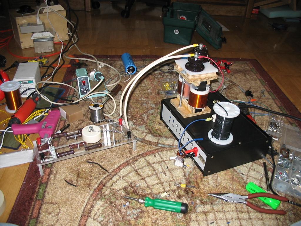
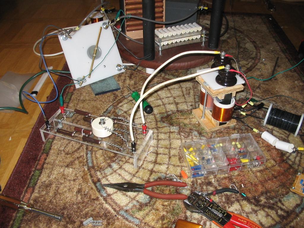
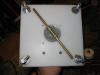
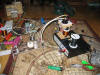 The
transformer and LC have been hot-glued (temporarily) to the top of the box.
To the left we can see a full-wave bridge (32kV 1A) and an LC filter after that,
this is used for running a tesla coil from the supply.
The
transformer and LC have been hot-glued (temporarily) to the top of the box.
To the left we can see a full-wave bridge (32kV 1A) and an LC filter after that,
this is used for running a tesla coil from the supply.
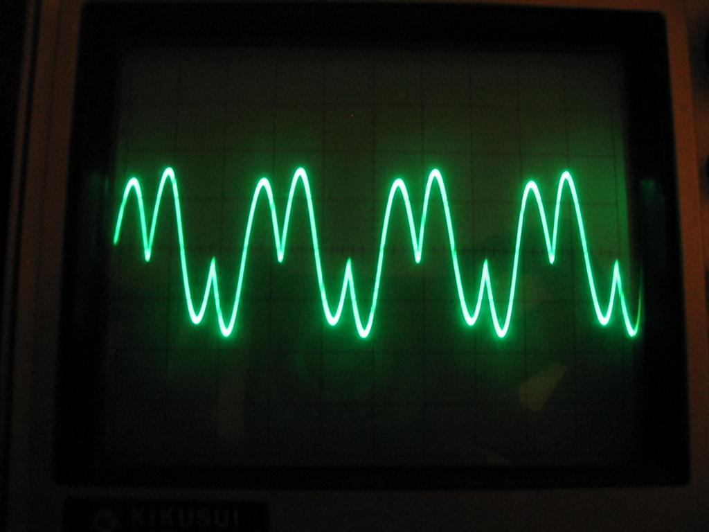
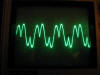 Here
is a real waveform of the primary current, we can see that it nicely matches the
predicted waveform from the simulation!
Here
is a real waveform of the primary current, we can see that it nicely matches the
predicted waveform from the simulation!
Failures:
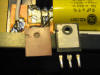
 This
failure was a result of (foolishly) operating with a half-wave rectifier on the
output of the transformer. I believe this may have caused saturation of
the transformer. Always use full-wave rectification on your transformers!
This
failure was a result of (foolishly) operating with a half-wave rectifier on the
output of the transformer. I believe this may have caused saturation of
the transformer. Always use full-wave rectification on your transformers!
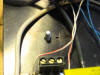
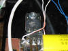
 Aside
from the usual IGBT failures, I had this interesting failure of the sil-pad
insulation between IGBT and heatsink. Apparently the pad was damaged when
i was operating the TC, which was grounded to the heatsink and it arced to the
IGBT! But it continued to work, even with a slightly scorched pad.
But the damage caught up, and eventually it broke down with a loud buzzing sound
(that was an arc between the IGBT and heatsink) until the fuse blew. There
was deep pitting in the heatsink. Replaced the pad and its good as new.
Aside
from the usual IGBT failures, I had this interesting failure of the sil-pad
insulation between IGBT and heatsink. Apparently the pad was damaged when
i was operating the TC, which was grounded to the heatsink and it arced to the
IGBT! But it continued to work, even with a slightly scorched pad.
But the damage caught up, and eventually it broke down with a loud buzzing sound
(that was an arc between the IGBT and heatsink) until the fuse blew. There
was deep pitting in the heatsink. Replaced the pad and its good as new.
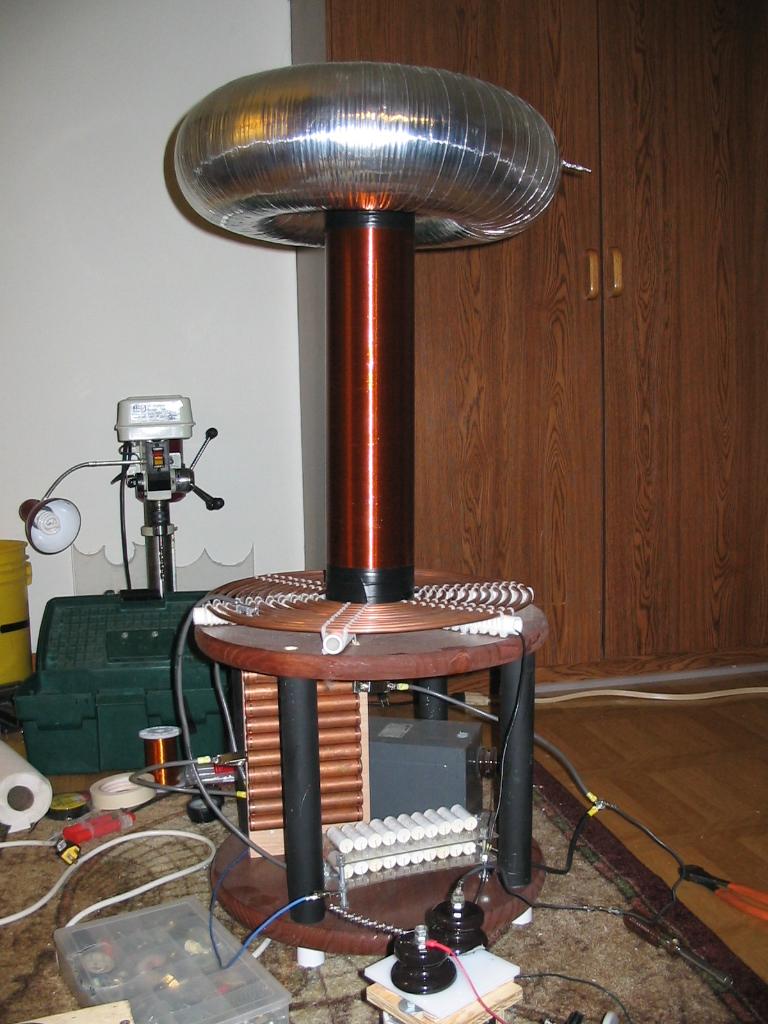
Initial TC testing:
The test coil uses a 30nF 16kv MMC, a 12 turn primary (18" OD),
a 4.5"x16" winding of 24awg, and a 6"x19" toroid and a ARSG (up to 400BPS).
 The
ARSG.
The
ARSG.
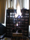
 You
can see the TC base in the back with the old static gap and 9kv 60ma NST still
installed (neither being used).
You
can see the TC base in the back with the old static gap and 9kv 60ma NST still
installed (neither being used).
 The
coil itself.
The
coil itself.
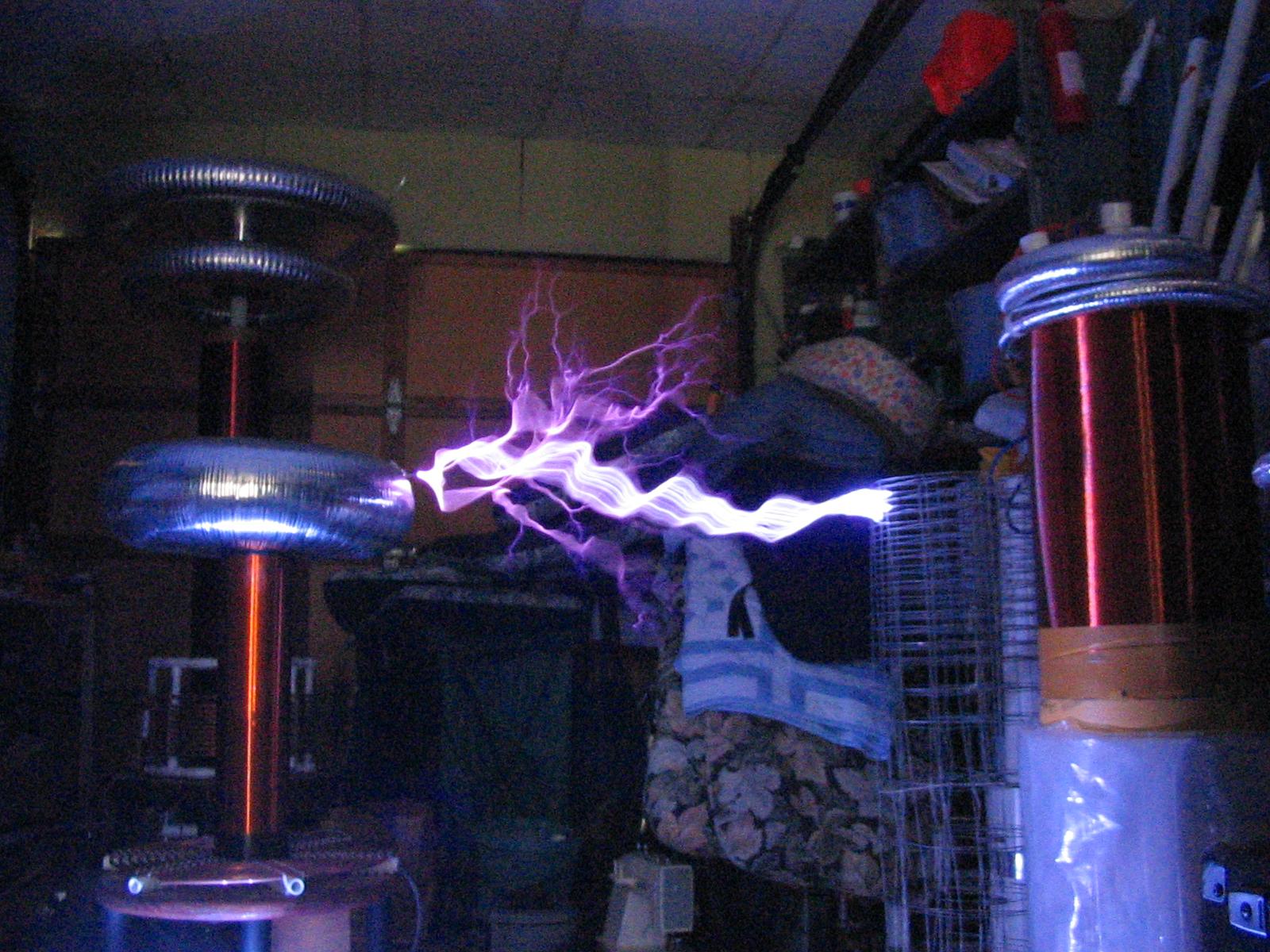
 Some
30" sparks. Nothing too impressive. I believe the poor performance
is due to the limited energy storage of the MMC. The transformer was only
running about 500W at this point. Better results to come later
(hopefully!).
Some
30" sparks. Nothing too impressive. I believe the poor performance
is due to the limited energy storage of the MMC. The transformer was only
running about 500W at this point. Better results to come later
(hopefully!).
More pictures:
 New
secondary coils, each has exactly 200 turns of 36awg. Output voltage is
around 20kVAC.
New
secondary coils, each has exactly 200 turns of 36awg. Output voltage is
around 20kVAC.
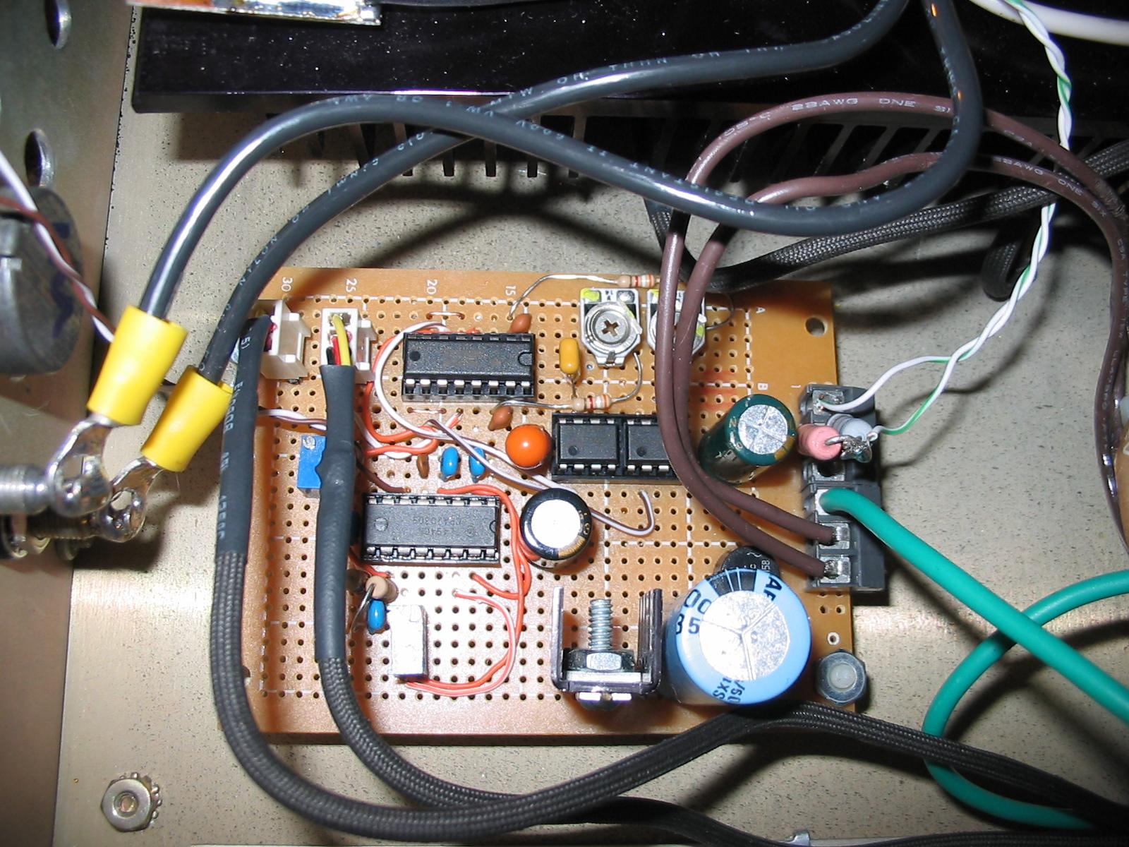
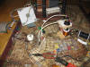
 Current
status of the control board. Note wiring to fans (black cloth wire).
Also added current control (just a fancier PWM control). Schematics to
come later.
Current
status of the control board. Note wiring to fans (black cloth wire).
Also added current control (just a fancier PWM control). Schematics to
come later.
 The
trusty H-bridge. Notice we used quick connects for the IGBT connections.
This was what we came up with after getting sick of unsoldering the IGBTs from
the board after each failure. Now IGBT replacement is quick (and slightly
less painful).
The
trusty H-bridge. Notice we used quick connects for the IGBT connections.
This was what we came up with after getting sick of unsoldering the IGBTs from
the board after each failure. Now IGBT replacement is quick (and slightly
less painful).