VTTC FAQ (Draft)
Updated 3/6/04
This FAQ is currently under construction. The material within may not be complete or correct at the moment.
1)What is a vacuum tube?
We can think of a Vacuum Tube (Valve, VT) as an electrical valve in which current flows in one direction only. Every tube has at least 2 parts to it. The Anode (more +) or 'plate' and the Cathode (more - ). Most tubes have a heated cathode. Heating is often done by use of a filament. In most tubes, the filament IS the cathode, they are the same exact piece of metal inside of the tube. The cathode can also be indirectly heated as in some larger tubes (not very common) where the cathode and filament are 2 isolated parts within the tube. You may have also heard of 'cold cathode' tubes. Cold cathodes are often used for lighting (neon lights) and not of concern to those wanting to learn about VTTC's.
Now back to our description of an 'electrical valve'. A valve passes currents in one direction only. In a vacuum tube we pass electrons from the cathode to the anode. A heated cathode emits electrons readily, and the anode accepts them. A tube with only an Anode and Cathode is known as a Rectifier, something that passes current in only one direction. Tube rectifiers are usually good for high voltages (300v+) and lower currents than we may find in common silicon rectifiers or diodes. Now, there is one crucial part to our valve that we could add, and that is some sort of control. Enter the Grid.
Imagine turning on your garden hose by turning the valve to slowly control the flow of water through it, this is exactly what the Grid of a vacuum tube does. The Grid is a mesh of wire that sits in between the cathode and anode of the tube. We control the electrical flow inside the tube by altering the electrical charge on the grid. If the grid is strongly negative (as in same potential of the cathode) then we have very little or no electrical flow since the like charges repel! So right now our tube is in a non-conductive state. But, if we change the potential on the grid to a more positive voltage, we start to increase the current flow from cathode to anode within the tube! A tube with an anode, cathode and grid is known as a Triode. Some triodes can have up to +600v on their grids and up to 5000V on their plates! The 833A triode is a good example.
There are many other types of tubes out there. The Tetrode has 4 elements, same as the triode but with an extra control element known as the Screen. Usually the screen is set at a + voltage (known as biasing) and will alter the operating characteristics of the vacuum tube. Many more screens and control grids can be added inside of the vacuum tube to get Pentodes etc. For a beginner, I suggest sticking with the basic triode as there are no screens to bias (which could get rather tricky).
Now that we have a basic understanding of a vacuum tube, we can approach a VTTC with intelligence.
2) A general idea of what is going on
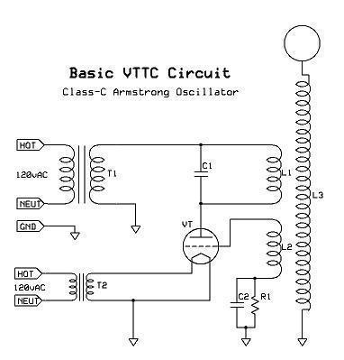
Lets take a brief look at how a VTTC works so that we have a general idea to keep in mind while we get into the nitty gritty later on. Basically with a VTTC, we are using a vacuum tube to act as a switch. The tube is in series with the current flow. We can follow it through easily. Starting at the top of the schematic we have our HV (T1) supply that then must pass through the LC tuned tank circuit (C1 and L1) and then through the tube (VT) to ground (which is also the return of our HV supply) Now, we must switch the tube on and off at a specific rate, that being the Fres of our secondary (L3). Of course, we will never be at the exact Fres of the secondary coil, but we must strive to get very close. When the coil starts up, a small amount of current flows through the tank (C1, L1) and through the tube. This excites the secondary coil (L3) and the grid coil (L2). The grid coil (L2) then sends a pulse to the grid of the tube. This turns the tube on and off at just the right times to keep the cycling going, and this is how the oscillator works.
3) Tank Circuit- What is continuous wave?
If you understand how to tune a typical spark gap TC then you really don't have much else to learn! If you are new to all of this then I suggest you read THIS site first.
A VTTC uses an LC tuned circuit (C1 and L1) just like a spark gap tesla coil. It may look different at first glance but really is similar. Lets look at the similarities and differences. In a spark gap tesla coil (SGTC) we have a capacitor in series with the tesla primary, but if we stop and think about what the spark gap does, we see that, when the spark gap is conducting, the capacitor is in fact in parallel with the primary inductor. Looking at a VTTC schematic, we see that the capacitor is already hard wired in parallel, and then the whole mess is switched to ground via the vacuum tube. Now that we see that a SGTC and VTTC both use LC tuned circuits we can begin to analyze the differences between the 2 circuits: the manner in which power is switched.
In a SGTC we use the tank cap for 2 reasons, 1 to form an LC tuned circuit and 2, to supply high current pulses to the primary coil. In a VTTC we have a much different story. There are no hundreds or thousands of amps jumping around, but just a rather high average current. With a SGTC we simply dump a bunch of power into the coil in one decaying pulse. With a VTTC, we drive the resonator in a different manner known as Continuous Wave (CW). The circuit pushes power into the resonator at EVERY cycle, meaning if you have a 400khz coil, the primary is transferring an equal amount of energy to the secondary 400,000 times a second! This is also assuming a filtered DC power supply (more on that later)
(insert picture of a damped wave from a SGTC and a continuous wave from a VTTC to show how mean power is the same but that the SGTC has its power distributed differently)
4) Grid Feedback- How does it work? (revised)
The most complex parts of the VTTC circuit are the grid feedback and grid leak system. It is what makes everything work together to oscillate. I hope to be in depth enough to give the reader a clear understanding but not to swamp him with complicated theory.
The VTTC schematic that is most commonly used is a tuned plate Class-C oscillator (in my case, a Series Fed Armstrong oscillator). You may have also seen Hartley oscillators mentioned elsewhere and are similar in operation to the circuit I use.
Here is how it all starts. Voltage is applied to the plate, thus pulling electrons from the cathode. The tube conducts, and as it does, the tank circuit is pinged. The primary drives the secondary, but also couples some energy into the grid feedback coil. This coil sends a strong negative pulse to the grid, turning the tube off. When this happens, the negative charge is stored in the capacitor of the grid leak circuit. This negative bias holds the tube off for the rest of the RF cycle. Eventually, the resistor bleeds off the extra charge, and the tube is allowed to conduct again (when the tank begins to reverse its oscillation cycle). This oscillation generates a strong negative bias. This happens at a rate of perhaps 350kc/s or whatever the tank is tuned to. This type of operation is known as Class C, and is highly efficient. The tube is actually only ON for perhaps 20% of each cycle!!!
(insert graphic showing tube conduction VS grid charge VS TC output)
Now, that this is fresh in the mind, I will discuss what the effects of larger or smaller resistance (R1) are in the grid leak system assuming a leak capacitor (C2) of 2nf (a typical value). With a very low resistance (of maybe 1k ohms or less) the tube conducts heavily and runs smoothly, here is why. When the tube is conducting heavily, the grid leak resistor is bleeding off the negative charge its picking up rather quickly, meaning, it takes longer for the emitted electrons to drive the tube back off. So this means that the tube is on for a longer percentage of each cycle, maybe up to 30% or so. Since the tube is conducting for a longer period of time, you can easily see why the coil is using more power! You can also see why the tube will run hotter with a lower resistor value.
What about a high resistance in the grid leak system? Well, the exact opposite happens. The negative electrons build (on C2) much faster and cut the tube off much faster. Conduction time may be only 15% or so (for typical VTTC operation). Less power is being processed and the tubes run cooler but the spark length often also suffers.
5) Power supply- AC, Level Shifted, Smoothed DC
If you have looked over other VTTC schematics you may have noticed that people use various methods of supplying the plate supply voltage. The most common is using a MOT (microwave oven transformer). The common MOT can produce ~2kvac at some 500ma or so, sometimes even nearing 1A output under some conditions (not recommended!). The MOT itself without any changes being made to it can supply your VTTC just fine. Since the tube only operates in one direction, the tube will simply be ON for the + portion of the AC cycle, and OFF for the negative portion, but still having a maximum of 2kv or so across the tube. This is what the schematic at the top of the page displays. This is fine, but, many large tubes can likely take up to 2X the MOT output voltage. If we can, we would like to utilize the tubes voltage capabilities.
Higher voltage is good for a few reasons: same power at lower current levels, can use a smaller tank capacitor value (to maintain a higher tank Z), and higher voltages seem to be more efficient overall at producing the best sparks from the TC itself. You could find a large plate transformer rated at several kV, or even use a small potential transformer or pole pig! These would likely be reserved for very large tube coils.
There is an easy solution to getting higher voltages from our MOT though: the level shifter
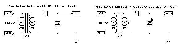
This is the same circuit that the microwave oven uses, but we reverse the diode to give a + voltage output rather than the negative voltage that the magnetron uses in the microwave oven. The level shifter will typically give 2X the peak voltage of the transformer. So for a 2kvac MOT we see: 2000*1.41*2=5640V!!! Ah, but wait, we have a rather hefty load on the output! Typically, under a moderate VTTC load, we can expect perhaps 4-5kvDC pulses from our level shifter supply at most. This is probably the next most common, and my preferred method of supplying the plate.
The final method is filtered or smoothed DC (and really, smoothed DC is the only condition where a VTTC IS CW!! Since with the 2 previous methods, the coil is actually off for at least half of the time (the negative portions of the AC input) But lets not have that confuse you). This would involve the use of a full wave rectifier and a large amount of filtering capacitance (several 10s of uF). This is probably the least favored by coilers looking for long sparks. The continuous power means LOTS of heating thus limiting the coil to a lower output. The best use for filtered DC would be if you wanted to audio modulate the coil, in which case, you don't want a loud 60hz buzzing in the background. Filtered DC will produce short, but extremely hot flame like sparks that just hiss. I have yet to run any of my VTTCs on filtered DC, though it is similar to running a SSTC with filtered DC (which I have done).
6) Impedance matching
Another very difficult concept that is helpful for understanding VTTCs. First, the brief explanation for impedance matching that finally sank in for me:
Assume you have available these 4 items on your bench:
(a) A series of eight fresh AA type 1.5 volt cells to create a total of 12 volts supply.
(b) A 12 volt heavy duty automotive battery - fully charged.
(c) a small 12v bulb (globe) of very, very low wattage. and;
(d) a very high wattage automotive high-beam headlight.
Now if we connect the extremely low wattage bulb to the series string of AA cells we would expect all to work well. Similarly if we connect the high wattage, high-beam headlight to the heavy duty automotive battery all will be well. Well for a time anyway. Both of these sets are "sort" of matched together. Light duty to light duty and heavy duty to heavy duty.
Now what do you think would happen if we connect the high beam headlight to the series AA cells and conversely the low wattage bulb to the automotive battery?.
In the first case we could imagine the high beam headlight would quickly trash our little tiny AA cells. In the second case our min-wattage bulb would glow quite happily at its rated wattage for quite a long time. Why?, therein lies my explanation of impedance. Consider it!
The heavy duty battery is capable of delivering relatively large amounts of power but the series string is capable of delivering only relatively minimal power. The first is a low impedance source and the other, in comparison is a relatively high impedance source.
On the other hand the high beam headlight is capable of consuming relatively large amounts of power but the miniature bulb is capable of consuming only minimal amounts of power. "
Text taken from: http://www.electronics-tutorials.com
Now, the difficult part! There are several impedance matches to be considered with VTTC design.
First is obvious: the match between the plate supply (T1) and the tank of the TC (C1, L1). This match is the easiest to envision. The impedance of the tank (or the Z load as it may be termed) should ideally be higher than the impedance of our supply. Meaning that, the supply has headroom in respect to powering the TC. See my VTTC Math page for equations to help determine the Z load of a VTTC (which often takes some guess work unless you have some great equipment on hand!).
Next is the impedance match between the primary and secondary circuits. I unfortunately am not the best person to explain this, and will admit to not having a very good understanding myself. I can still generalize cant I? The impedance of the tank (primary circuit) has been determined from the previous paragraph. Now, in order to optimize things, we would like to have it that, all of the energy that the primary can supply, will get used up by the secondary coil in the form of long sparks. Now, the secondary Z is made up of 3 components, its wire resistance, its inductance, and its self capacitance. The primary of course determined by its resistance (almost nothing, so not even considered), inductance and of course capacitance. With VTTCs, this match is almost always poor, and well, there is not much we can really do about it since tubes have a limited amount of current they can process etc.. Truthfully, if one is to care so much about this topic, he/she will find the means to research it. My goal was to bring some light onto it and perhaps get people thinking.
There is even such ways to match your top load with your secondary coil, but this is quickly getting out of the scope of this FAQ.
7) Choosing a coil- How does Fres seem to effect things
Just some general things I have noticed when using setups with various frequencies and sizes.
1) When Fres drops below 300khz, the sword-like characteristics of the sparks seem nearly non-achievable . In a recent test (using a SSTC as a driver) I tried various coils that I had on hand. My 350khz secondary from the dual 833A VTTC produced very sword-like sparks as expected. Next, I tried a 300khz secondary, it produces a somewhat spoiled sword-like spark, but still desirable for my needs. I also tested this coil on my dual 833A VTTC, and got very similar, somewhat spoiled sword sparks from the coil. Then, finally I tested a 190khz coil on the SSTC driver, and it produced gnarled sparks. I did not test this on the VTTC, but in an old experiment using a rather LF coil, I got similar gnarled sparks. This suggests to me that the spark appearance is dependent on the resonant frequency of the secondary coil. I have yet to see a LF coil produce strong sword-like sparks.
2) It seems that smaller coils produce smaller sparks compared to larger coils at the same power levels. I think, as long as the coil is appropriately sized for the power, things will work out well. Of course, we do not want a 3 foot tall coil that makes a 12" spark. I would say a good generalization for most secondary coils is:
8-10" tall for sparks up to 8"
10-12" tall for sparks up to 20"
12-18" tall for sparks up to 32"
20"+ tall for sparks greater than 32"
8) A real VTTC circuit- What's all that extra stuff???
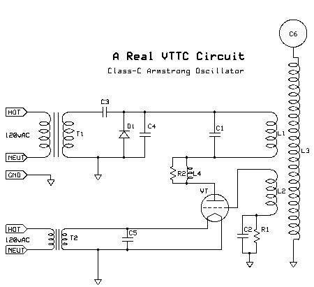
We already know what T1, T2, C1, C2, R1, L1, L2, L3 are, but there are several other components added into this schematic that should be discussed.
C3 and D1 make up the level shifter circuit already described in the section about power supplies.
C4 is an RF bypass capacitor. In RF circuits, capacitors usually pass HF AC, and block DC. In this case, we want to pass any RF that may be there from tank oscillations so that they don't damage the power supply (especially that diode!). The bypass cap is usually small (1-5nF or so at 10kv). Ceramic disk caps work fine here.
R2 and L4 make up a high frequency choke. In the event of a tube arc (an arc actually within the vacuum tube due to excessive voltage between grid and plate) there can be some strong high frequency (in the MHz) oscillations set up. This RL circuit kills these oscillations, protecting the tube (to an extent) in this event. Typically, R2 is between 20-100 ohms at a few watts (usually does not heat up, but we want it physically large). Then, L4 is actually wound around R2 (that is why R2 must be about 1-2" in length). L4 should have some 10-25 turns. Both components are non-critical, hence the rough guidelines.
C5 is another bypass capacitor. Since we cannot simply ground both legs of our filament, we need to have this bypass cap that will act to pass any RF through it (to the grounded leg). This cap should be in the 1-10nF range at a few hundred volts.
C6- optional, but I find that it always increases the performance of my coils. C6 is simply the top load or toroid. I like to use small toroids as not to load down the coil excessively. Large toroids seems to cause harsh kickback so I strongly discourage the use of large toroids.
9) What are some good tubes to use?
Some of my personal favorite tubes and why:
811A- it can be used for a decent amount of power output, runs good at MOT voltages (2kv) and is dirt cheap ($14 new). Also see the 572B which is very similar but with a graphite plate, and much more expensive.
810- Its got a tough graphite plate and if setup just right, will take some 4kv without much trouble. The graphite plate allows it to run longer.
304TL/TH- A beefy tube rated for lots of current on the plate. Good for pulse work (staccato). Its got a great look to it too. Downfall, they are old, and the filaments will crack from vibration alone!
833A/C/D- The 833A is just a great tube overall and can output up to about 1kw in class C. The C and D versions have graphite plates that make them extra tough for over 1kw. They do come with a price tag though, usually $90 new for an A, and a few $$ more for the C.
There are of course many other tubes that will work in VTTC use that I have not mentioned... a few others: 4-250A, 4-125A, 813, 803, 3-500z, and well, most other power tubes with at least a kV rating and some 10's of watts of plate dissipation. Small tubes can in fact be used for very small VTTCs that operate into the MHz.
10) Part criteria- Tolerances, specific characteristics
I will go over each part of the typical VTTC and explain what qualities each should have for reliable use.
--- Plate supply- rated for the maximum ratings of the vacuum tube being used. Perhaps rated for higher voltage than the tube if you like to push things like most people do.
--- Tank cap- I have used high quality doorknob capacitors (the common cheap ones are no good usually at high power). Mica of course being highly recommended. Also, for precise tuning, a variable air cap under oil, or a variable vacuum cap would work great.
--- Primary coil- For powers under 500W, 14awg is good enough. 500W-2000W needs 12awg or better. I don't know much about power levels above that, but I assume you would eventually want to use copper tubing like SGTCs do. I find no difference in using solid or stranded wire, so I use stranded.
--- Grid coil- I like to wind them using magnet wire of 24awg, but regular hookup wire would work fine also. Keep in mind that the spacing etc.. will effect its properties, so having the grid coil on a slide able form is a nice so that you can adjust its coupling to the primary coil.
--- Secondary coil- already discussed a bit. For power less that 500W, 30awg should be acceptable. 500W-1000W would probably use 28awg or better. Up to 2kW, I suggest at least 26awg, maybe 24 is better.
--- Filament supply- usually AC. Since the cathode is grounded, hi-pot ratings are not required. Try to keep the tolerance close on this. Its somewhat less harmful to run just over the tubes rated voltage than just below. I run the 833As at 10.2v, they are rated for 10.0v
--- Grid leak capacitor- most low inductance capacitors will work. 3kv is good for voltage. Small ceramic disk caps work at lower powers. Doorknobs will be nice for higher powers >1kW.
--- Grid leak resistor- value depends on the tube somewhat, but I would say that 100W is a good starting point for smaller VTTCs. Variable resistors are very nice to have. I use a 150W resistor bank on the dual 833A coil and it gets very hot at some 2kW.
--- RF bypass on the plate supply- needs to be rated for 2X the voltage of the supply. You can get by with ceramic disk, but doorknobs are likely better for higher powers. 1-3nf is enough capacitance.
--- RF bypass on the filament- 1-10nf usually at a few hundred volts. Most high quality caps will work fine, even ceramic disk seem ok. Poly film caps would be excellent.
11) Staccato- how does this benefit me?
The staccato controller (developed by Dave Sharp, John Freau...) is a very nifty way of reducing power draw but maintaining spark length from a tube coil. Staccato can only be applied to AC fed or level shifter supplied coils since it depends on the fact that the tube is only ON in pulses. Keep in mind that, these pulses (the + portion of the AC input) are all equal. Also, since there is a considerable amount of OFF time between the pulses, spark growth is not much of a concern. So what the staccato does is, turns the coil ON for a pulse, then leaves if OFF for an independent (controllable) number of proceeding pulses. In this manner, we can range the output from a mere 1 pps (pulse per second) to 60 pps. So, the average power can be reduced dramatically, but the actual spark (generated from a single pulse) is the same.
Perhaps the best benefit is the reduced heating of components allowing everything to run longer. We also gain a very interesting visual and audible characteristic. The coil can sound like a helicopter at some pps settings. At 30 pps, the coil roars a deep bass tone at high power that is very nice sounding. The visual effects are just as interesting. You can see the detail in a single spark at the lower pps settings, or get a bush of sparks at higher pps settings.
12) Other modes of VTTC operation- sputter mode, tuned grid
There are 2 other driving methods for VTTCs that I know of.
Sputter mode- This mode of operation is similar to staccato in that the spark is interrupted but in a different way. Sputter mode is achieved by using insanely large values for the grid leak system to get a grid blocking effect. What happens is, the grid pulls current on an oscillation. Since the capacitor and resistor are of large values, it holds the tube off for longer than it might normally. My first VTTC was a sputter mode type and used a .03uf and 50k ohm resistance for the grid leak values. This caused the coil to produce a spark about 12,000 times a second! It was awful sounding though as it screeched away. The sparks were thin and purple. Interesting indeed, but not as nice as a normal VTTC. When using sputter mode, its usually best to supply the coil with filtered DC so that you get a consistent output. There is a big drawback to sputter mode operation. The chance is high that the grid is allowed to turn back on at a bad time and cause kickback, and perhaps a tube arc. This site uses a sputter mode design.
Tuned grid- an interesting design that I have only seen employed once, uses a tuned grid rather than a tuned plate. This mean, the tank has no capacitor! But rather, the grid is tuned to the secondary coils resonant frequency. I'm not sure that this design would scale up well, but it does indeed work. This site has a tuned grid VTTC.
13) Spark length
Its very common that VTTCs have much less in the way of spark length than a SGTC of the same power. This is due to the CW mode of operation. John Freau developed a rough formula for figuring SGTC spark length for high performance coils: spark length = 1.7*sqrt(power input). He also developed a similar equation for VTTCs: spark length = .5*sqrt(power). Spark length is in inches and power is in watts.
14) What are some other good web resources?
I have created a list of sites that have at least a trace of information about tube coils. I will also include some tube databases and some links to oscillator theory etc..
| Daniel McCauley | http://www.spacecatlighting.com/ |
| Teslina Site | http://www.geocities.com/teslinasite/ |
| Ross Overstreet | http://hot-streamer.com/ross/ |
| Sue Gaeta | http://community.webshots.com/user/sgaeta |
| Carl Willis | http://www.angelfire.com/electronic/cwillis/index.html |
| Alan Jones | http://personal.atl.bellsouth.net/a/j/ajones18/ |
| Simon Winder | http://www.robotbugs.com/robotbugs/sparks/vactesla2.htm |
| Mazzilli Vladimiro | http://www.pupman.com/current/vladi2/index.html |
| John Freau | http://hometown.aol.com/futuret/page3.html |
| David Trimmel | http://chaoticuniverse.com/webdoc2.htg/Tubez.htm |
| Of course me! | http://www.hot-streamer.com/srward16/ |
| Oscillators | http://www.infodotinc.com/neets/book9/35c.htm |
| Everything! | http://www.electronics-tutorials.com/ |
| Tube info | http://www.radau5.ch/valves.html |
| Tube Database | http://hereford.ampr.org/cgi-bin/tube |
| 'nother database | http://tdsl.duncanamps.com/index.php |
15) VTTC Math
There is very little out there for VTTC design equations. I have been corresponding with John Freau for a while now, and he has given me several equations, and rules of thumb that may help others when they are designing a tube coil. I will try to present them as clear as I can. Nearly all of the equations and information were sent to me from John Freau. Enjoy!
Many of the calculations for the primary and secondary coil parameters can be figured using Bart's Java TC calculator. I use it often, and its quite accurate, though I sometimes find the tank likes to be tuned a bit lower than Java TC would suggest, so keep this in mind (I like to add an extra 15-20% of winding to all of my primary coils). So you may need to use the program with these equations presented below.
It is very difficult for me to specify an order to these calculations, so they may not be presented in the best form, but I will try to make this logical. I think first, one should decide on an secondary and primary coil and dimensions. For example, if you plan on a 24" spark coil, use a 3.5" x 12-17" secondary with 28 or 26awg respectively. Add in a small toroid. Make the primary roughly 2X the secondary diameter (not really a rule, but it seems to work ok) and use at least 15 turns (its probably better to have 20 or more). This is only an example! There are many designs that may work, but I will use my dual 833A coil for all examples. You may need to juggle the equations around to arrive at a design that meets your requirements.
| Q=R/X | Ex. Q=2083ohms/200=10.46 |
| X=primary reactance (Ohms) R=Load impedance of the tube |
| X=2*Pi*F*L_pri | Ex: X= 6.28* 400,000hz*(80uh/1000000)= 200ohms |
| X=Primary reactance (ohms) F=Secondary resonance (hertz) L=Primary could inductance (henrys) (use JavaTC) |
| R=V/2I | Ex. R=5000V/1.2A=4166ohms |
|
V=Plate supply voltage (volts) I=Plate supply current (amps) |
This assumes 2 tubes, both at about 300ma. So that's 600ma
from the plate supply. Note: You need to simply assume what current you want the tank to pull from the plate supply, use the tube spec sheet to find the maximum plate current and go from there. This is not an exact science. |
| R=V/4I | Ex. R=5000V/2.4A= 2083 ohms |
|
V=Plate supply voltage (volts) I=Plate supply current (amps) |
I will use this value for all other equations. |
| C_tank=Q/2PiFR | Ex. C=10.46/(6.28*400,000*2083)= ~.002uf (after multiplying by 1,000,000) |
|
C_tank=Tank capacitor (farads) F=Resonant frequency (hertz) R=Tube load impedance (ohms) |
Note that I got my Q from the first few equations. |
| Q=2PiFRC | Ex. 6.28*400000hz*2083ohms*(.002uf/1000000)=10.46 |
|
C_tank=Tank capacitor (farads) F=Resonant frequency (hertz) R=Tube load impedance (ohms) |
Note: This equation is simply rearranged to solve for Q |
So you see, these equations are all interrelated, so you may need to further manipulate them to come up with a good design. Use them as a general guide, not as a rule. VTTCs are actually rather unstable oscillators... some say that is the key to their long sparks. I don't think any simple set of equations could pin down the perfect design so don't fret over the math!
Questions? Comments? Suggestions? Complaints? Send them to me at : steve.ward(at)gmail,com
Thank you,
Steve Ward