The Micro SSTC
Page created on 11/28/03
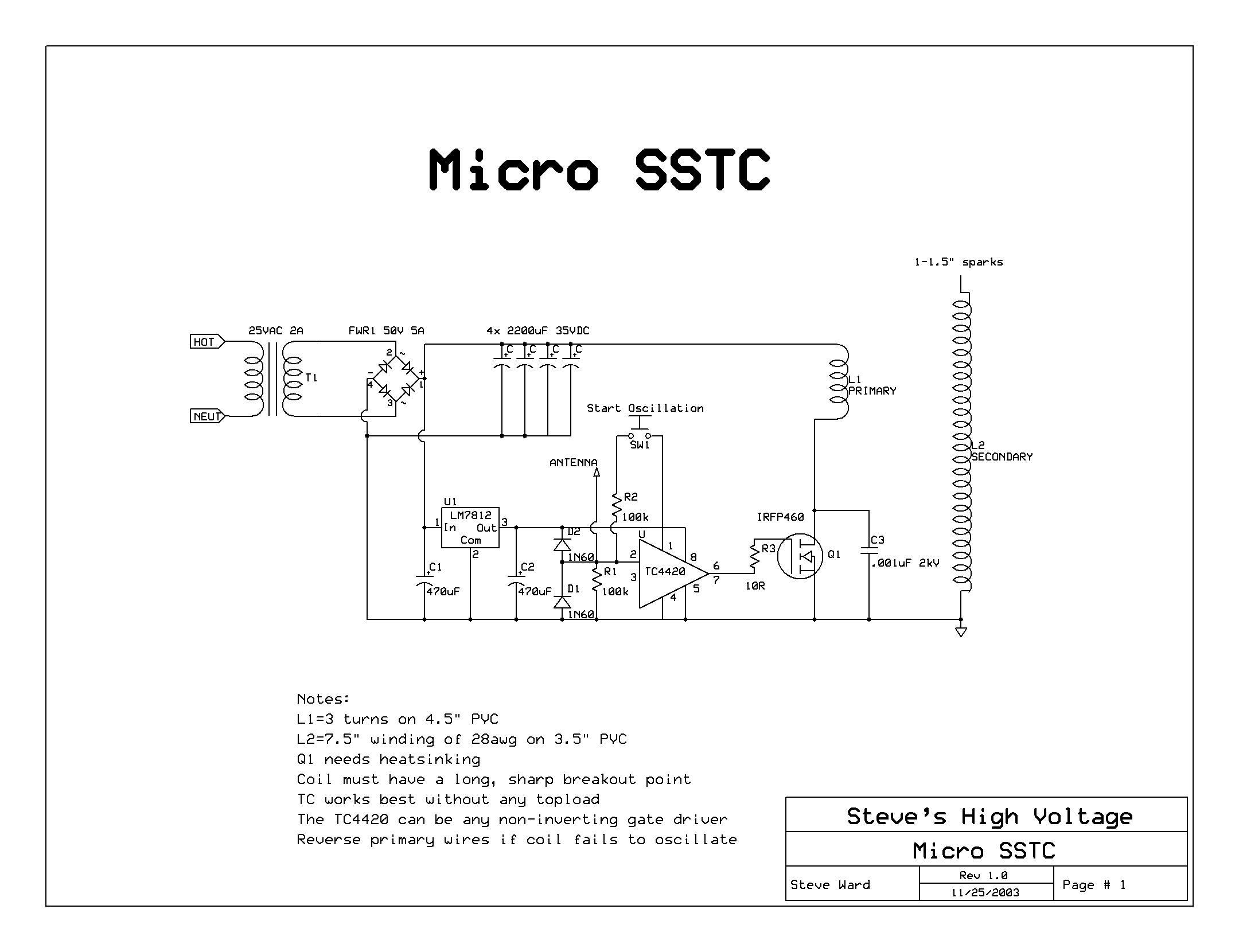
Here is a nice simple project that is incredibly simple (compared to a typical SSTC) and will work well with small high frequency coils. It is possible to build this coil in just a day or two, but it took me several days to decide on exactly what I wanted from the coil, and therefore to finish its design to my liking. Here is what I came up with:
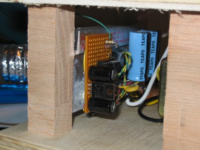
Explanation of this circuit: Basically we have a 25V transformer with full-wave rectification and filtering. This is our main 30VDC supply. Tapped into the supply through a 12V voltage regulator is the gate driver supply. Basically, the antenna takes feedback from the secondary coil and the gate driver chip acts as a comparator and amplifier. To get oscillation started there is a small push button that injects a high signal into the gate driver. This pulses the primary and causes the secondary to oscillate for a moment. The antenna picks this up and then the oscillation becomes rather stable pretty quickly. Note the 2 diodes on the pin 2 of the TC4420. Their purpose is to protect the chip. If the voltage from the antenna exceeds 12V, the top diode clamps to the + rail. If the voltage swings more negative than 0V, then the lower diode clamps it to ground.
I decided that I did not want a push button to start the oscillation since drawing arcs may disrupt the oscillation and cause the coil to turn off. So what I did was add a 555 chip that runs at I think 300khz or so. The signal from the 555 is constantly being fed into the gate driver, but once feedback is received, it takes over and switches to the resonant mode. Now we can pull arcs all we want and the 555 will keep kicking the coil back into oscillation. Here is the updated schematic and what I actually use in the final design.
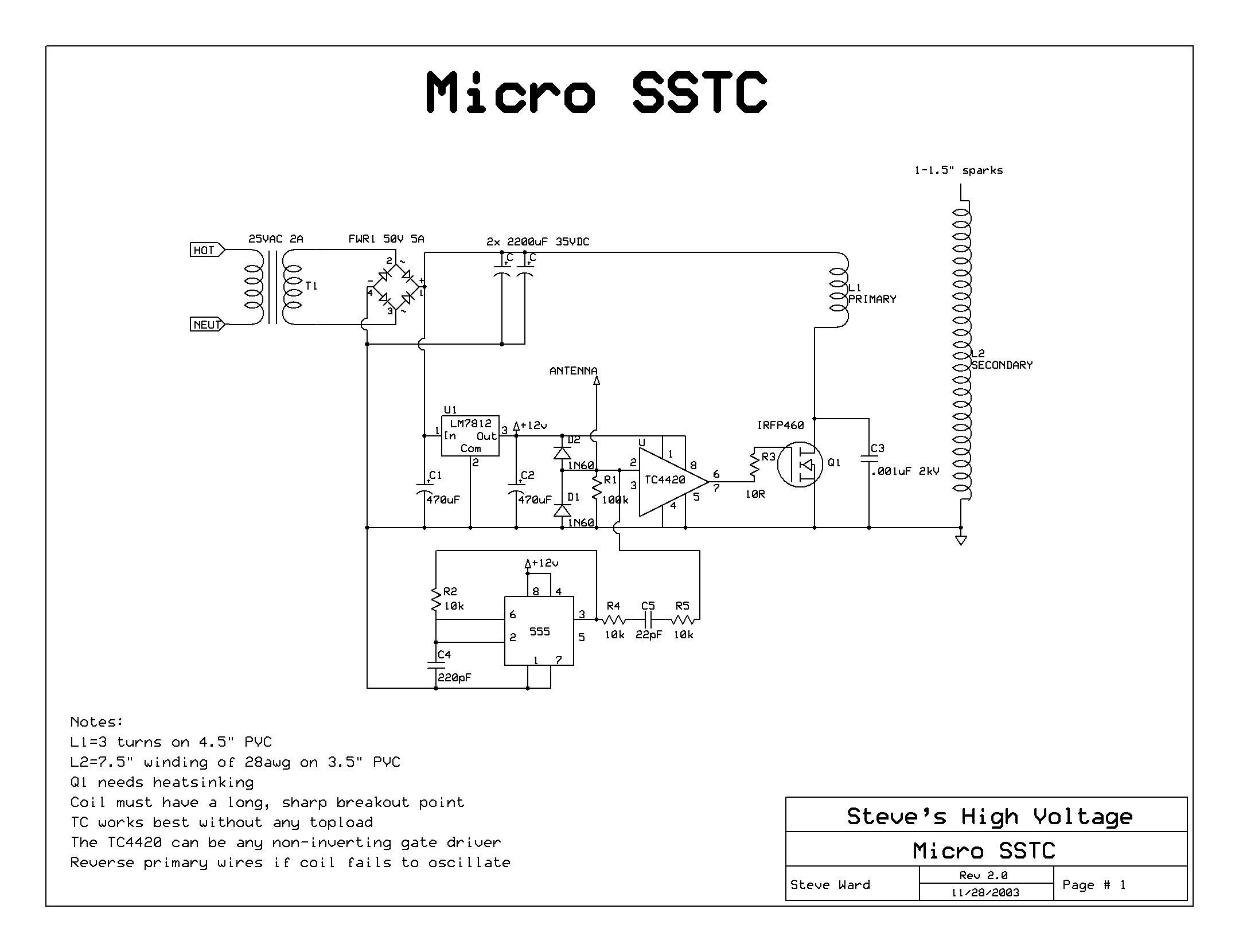
R4, R5, and C5 basically weaken the signal from the 555 so that the feedback signal will easily override it.
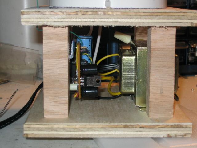
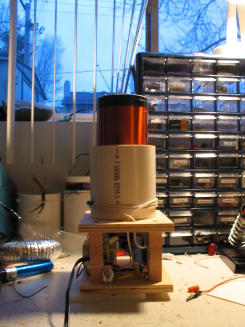
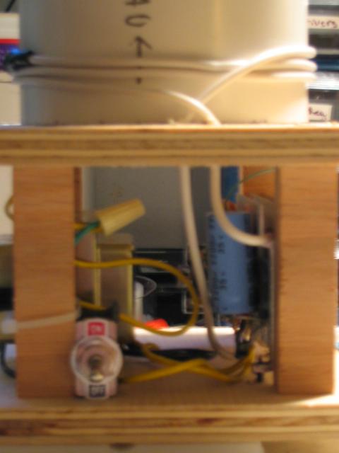
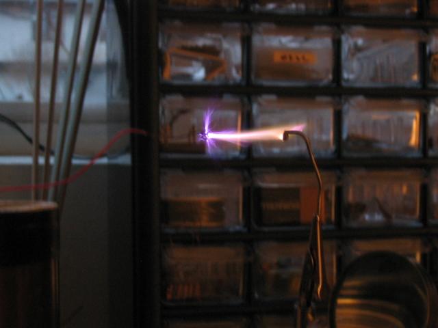
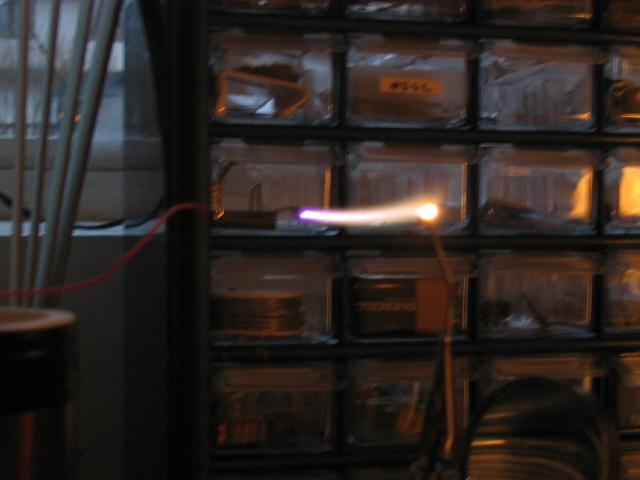
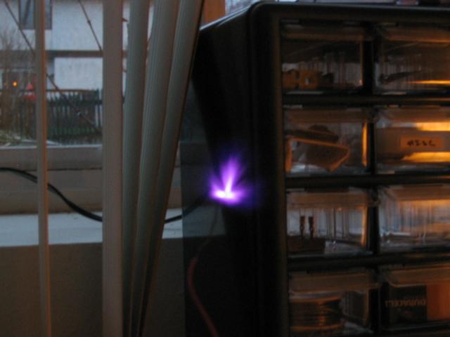
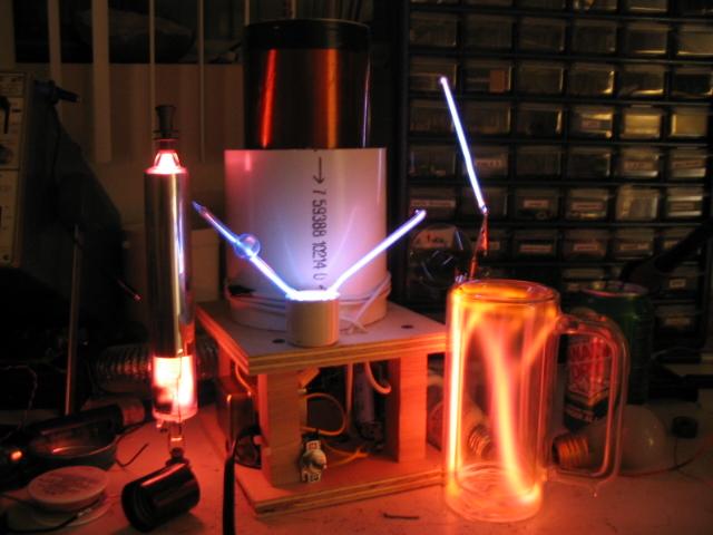
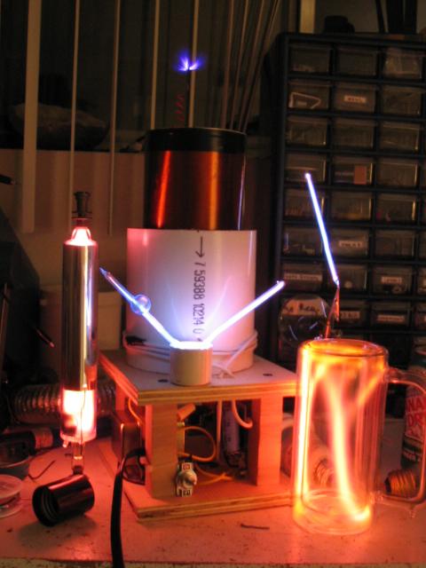
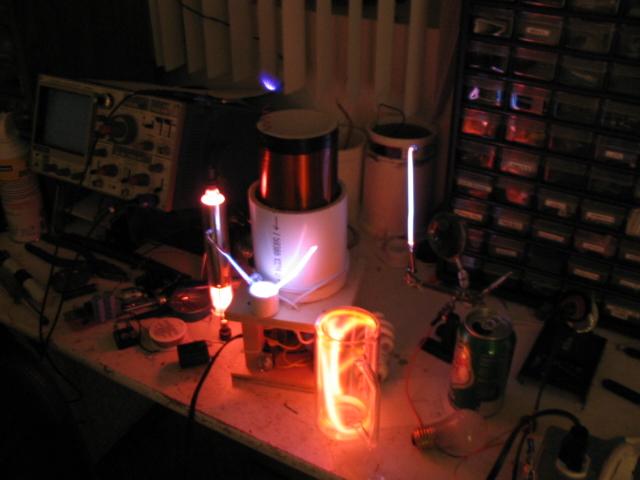
Here is the final result of my efforts (sparks are about 1.5" long max. Coil dimensions are 5.5x6.5x12.25"):