DRSSTC-1
Update 12/15/05 - scroll to bottom of page for latest pictures.
CURRENT SPECS
| Electronics | H-bridge of 40N60 mini-brick IGBTs. Controller schematic is shown below. |
| Tank Cap | 6 parallel strings of 2 series .15uF 2kV caps (942C series by CDE). Total: 450nF 4kV. |
| Primary | 7 turns of .25" cu tube. 11" diameter form, .2" spacing between turns, tapped at 6.5 turns. |
| Secondary | 6.5"x21" winding of 30awg magnet wire. Single coat of epoxy for protection. |
| Toroids | Lower is 2.5"x12", upper is 24"x6". |
| Filter capacitance | 2 series 22,000uF 200VDC electrolytics for 11,000uF at 400VDC. |
| Best Spark | 80" point to point. |
| Power consumption | 1200W with 72" discharges. |
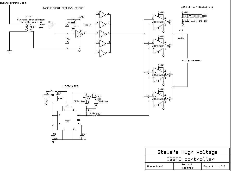
This first DRSSTC of mine evolved from the ISSTC work I had been doing at the time. Talking with Jimmy Hynes, who built the first DRSSTC, I decided I would give it a try, though with some changes from his design. Jimmy's DRSSTC used an oscillator to generate the high frequency signal that drives the coil (about 66khz for his coil, I believe). Since I'm not a big fan of using VCOs to tune tesla coils, I would use feedback from the secondary coil itself, ensuring that my driver was always in tune. I would then have to tune the primary circuit to this operating frequency. My feedback design started out very simple, and is seen below:
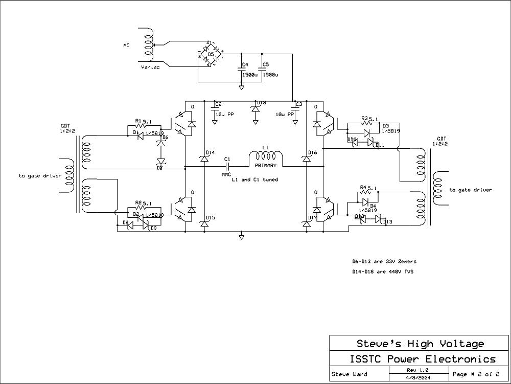
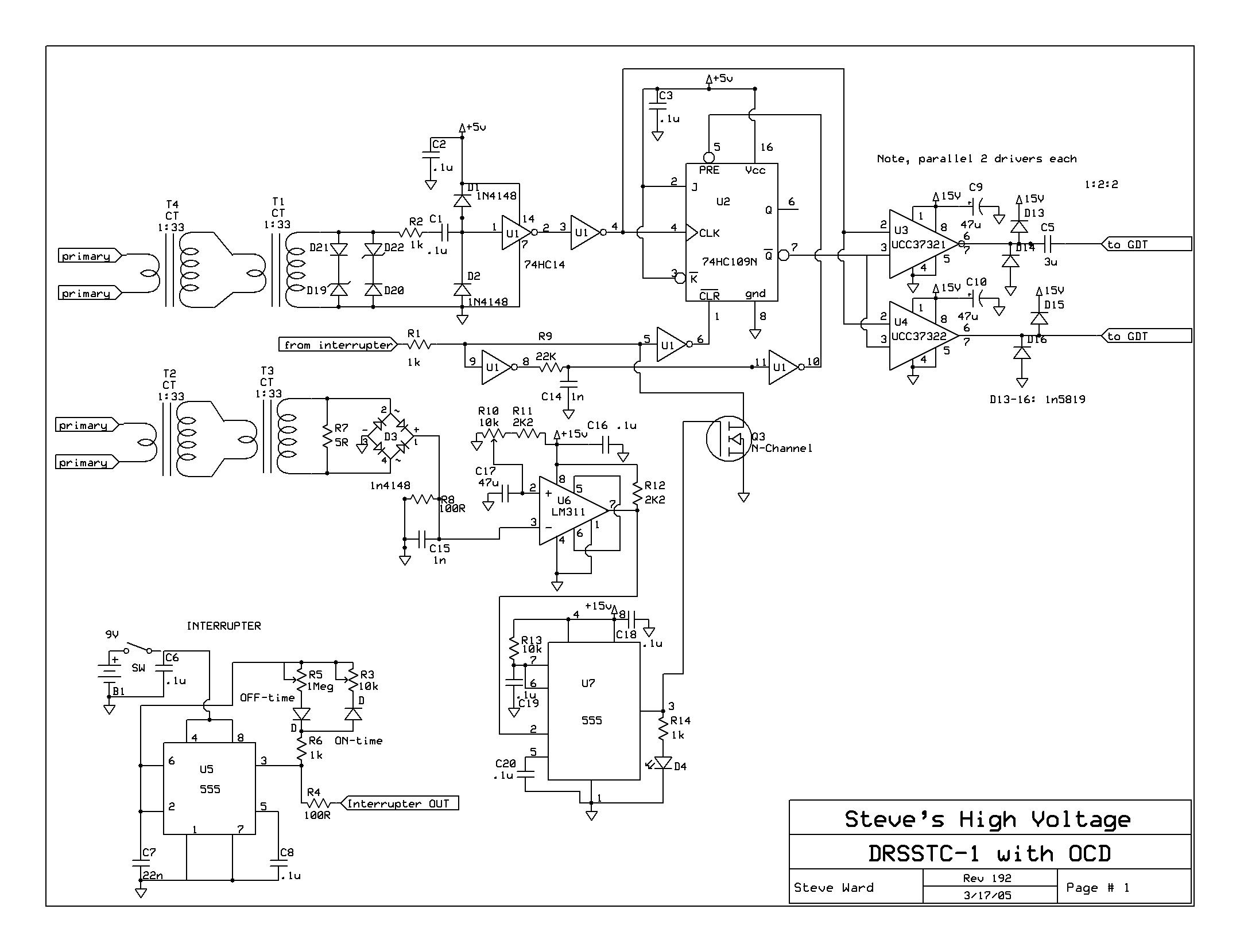
The first schematic was what I originally used for my DRSSTCs. The second schematic is just a standard H-bridge, nothing too special there. I eventually made an important change to this very basic controller. The change was the addition of a JK flip flop, which would synchronize the interrupter turn off to the feedback zero crossing. This is important because with out this, the interrupter can disable the gate drivers during an RF half-cycle, where current could be very high. DRSSTCs rely on soft-switching, due to the resonant load. We try to avoid hard switching the several hundreds of amps that may be flowing through the primary circuit, as this is very hard on the IGBTs. Anyway, the flip flop ensures that this should not happen. Below is the schematic (updated 3/17/05):
I still use the same basic schematic for the H-bridge, except now I use a voltage doubler at 140VAC, using a pair of 22000uf 200VDC electrolytic capacitors. These capacitors are much larger than needed, but they are what I had on hand.
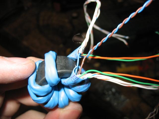 Here
is how I make my GDTs. I take some cat-5 networking cable, and wrap 10
turns of it around a ferrite core. I then parallel all of the "white"
conductors, and then series up pairs of the "color" conductors. This gives
2 outputs, and a 1:2:2 transformer with very high primary to secondary coupling.
Here
is how I make my GDTs. I take some cat-5 networking cable, and wrap 10
turns of it around a ferrite core. I then parallel all of the "white"
conductors, and then series up pairs of the "color" conductors. This gives
2 outputs, and a 1:2:2 transformer with very high primary to secondary coupling.

 Here
is my current H-bridge. It is made from copper clad, etched by hand with
my dremel rotary tool. Both sides of the clad are used in parallel to
increase conductor surface area.
Here
is my current H-bridge. It is made from copper clad, etched by hand with
my dremel rotary tool. Both sides of the clad are used in parallel to
increase conductor surface area.
Here are some older spark photos. Some sparks were as long as 55" in length. Notice in one pic, the blue illumination of the background. I caught an IGBT failure on camera, and that blue light is from the fuse exploding violently!

12/18/04: This project is actually still under construction. This is why there are not many construction pictures... because the coil has had many changes made to it. What brought about this construction? Well, my desire to try new things. Recently I have been curious to try a lower tank impedance (Z=sqrt(L/C)). So I quadrupled my tank capacitance to .3uF, and reduced my primary to 4 turns. Additionally, I built a new, 6.5" OD secondary using 26awg, the whole thing runs at around 130khz.
 Here
is the beefy voltage doubler consisting of 2x 22000uf 200VDC capacitors.
Here
is the beefy voltage doubler consisting of 2x 22000uf 200VDC capacitors.
 Here
is the new control board I etched for this coil. Notice how I stacked the
gate drivers. This is ok in a pulsed application like this, where driver
heating is not considerable. You must not do this in a CW system!
Here
is the new control board I etched for this coil. Notice how I stacked the
gate drivers. This is ok in a pulsed application like this, where driver
heating is not considerable. You must not do this in a CW system!
 Here
is the MMC, 6 parallel strings of 3 series .15uf 2kv CDE caps. .3uf 6kvDC
total rating.
Here
is the MMC, 6 parallel strings of 3 series .15uf 2kv CDE caps. .3uf 6kvDC
total rating.
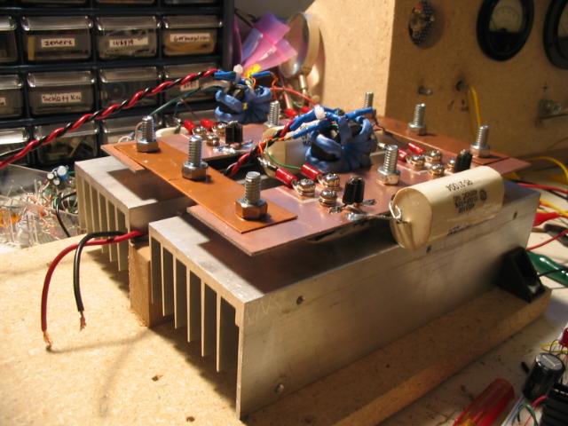
 Here
is the mess of electronics. Notice the large amounts of decoupling
capacitors on the power rails of the H-bridge.
Here
is the mess of electronics. Notice the large amounts of decoupling
capacitors on the power rails of the H-bridge.
 I
had to hack up my old primary to make it work for this coil.
I
had to hack up my old primary to make it work for this coil.
 And
here is the whole thing. New 6.5"x22" secondary (epoxy coated) with a
2"x12" and 6"x19" toroid stack.
And
here is the whole thing. New 6.5"x22" secondary (epoxy coated) with a
2"x12" and 6"x19" toroid stack.
Spark photos with the new setup will come soon.
1/13/04:
I ran the new setup (6.5"x22" secondary, .3uf MMC) in the garage yesterday and recorded some data. The % of VAC is of 140VAC input which is then doubled to 400VDC max. Power into the coil was recorded at the power outlet. Notice how poor the efficiency is as the ON period increases!
| Spark Length (inches) | Power into the coil (watts) | Burst duration (uS) | Breaks per Second | % of VAC input | Comments |
| 48 | 625 | 100 | 120 | 75 | |
| 48 | 725 | 125 | 120 | 66 | |
| 48 | 810 | 150 | 120 | 60.5 | |
| 48 | 930 | 175 | 120 | 60 | |
| 48 | 1200 | 200 | 120 | 60 | blew 10A fuse |
| 60 | 800 | 110 | 120 | 90 | vertical arc to ceiling |
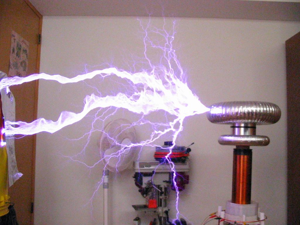
3/16/05:
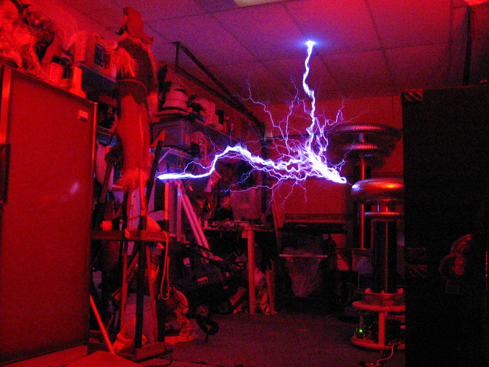
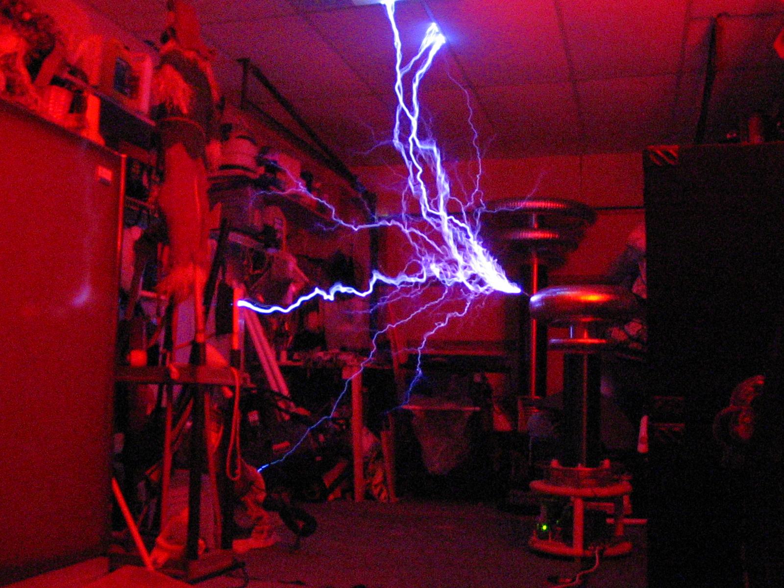
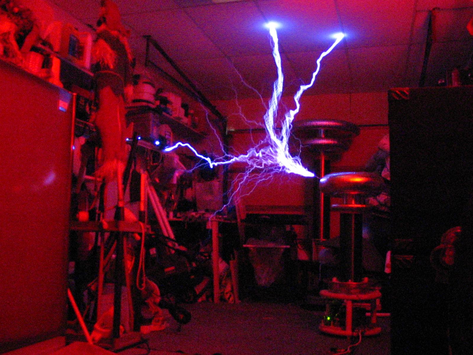
A lot has changed. New secondary (6.5"x21" 30awg) and now running on primary feedback. Also a new MMC, 5 strings of 2 caps in series for .375uF. A new primary was needed to tune (requires 7 turns now). The primary is tuned to 55khz, the secondary Fr is about 75khz. Sparks easily hit 6' with measured 650A+ in the primary circuit. I tested these IGBTs to over 1000A at 95khz so this should be no problem at all. Everything runs nice and cool at 55khz and the sparks are pretty darn hot! Enjoy some pictures from today (notice the red LED on the base of the coil, indicating that the overcurrent circuit tripped). The coil was running 120bps and 150uS on period.
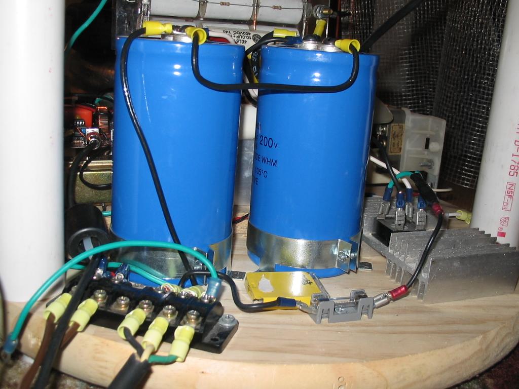
6/18/05:
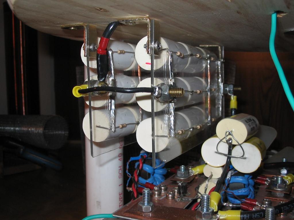
I recently had an MMC failure when pushing the coil to 200uS operation (that is 11-12 cycles per bang). The caps got very warm and one of them had a massive over voltage failure (which I suspect may be due to the heating). In any case, I constructed a new MMC (though it uses old caps from the old MMC):
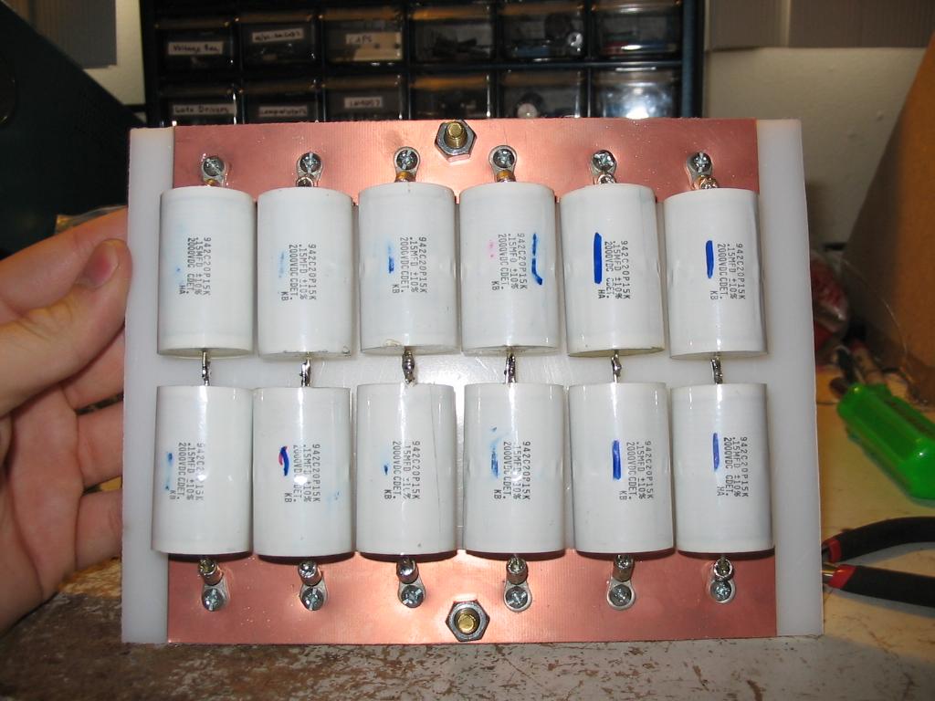 This
MMC is 6 parallel strings of 2 in series. This yields 450nF at 4kv.
This
MMC is 6 parallel strings of 2 in series. This yields 450nF at 4kv.
So lately, Terry Fritz has been developing his "ScanTesla" program which is partially designed for DRSSTCs. The idea is to make a program that will perform hundreds of simulations varying the tuning and coupling until it finds an optimum design. Anyway, his program suggested that my original coupling of .25 was good, but that .18 might make bigger sparks ;-). So I raised the secondary 1.5" higher. The coil responded well to this and I managed to catch a few 80" strikes running at 8 primary cycles. This got me doing some simulation work of my own. I wanted to find the primary bang energy for a range of primary cycles:
|
Primary Cycles |
Bang Energy |
|
6 |
8.7 |
|
6.5 |
9.6 |
|
7 |
10.6 |
|
7.5 |
11.6 |
|
8 |
12.6 |
|
8.5 |
13.5 |
|
9 |
14.5 |
|
9.5 |
15.4 |
|
10 |
16.4 |
|
10.5 |
17.3 |
|
11 |
18.2 |
The bang energy also includes primary losses.
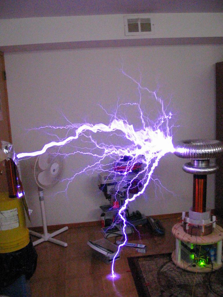
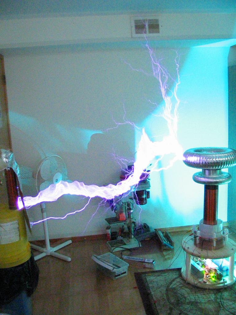
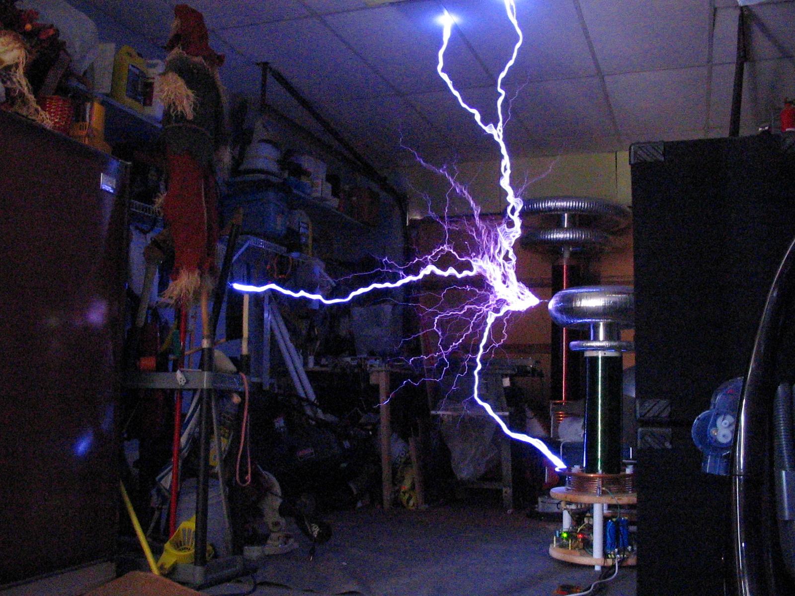
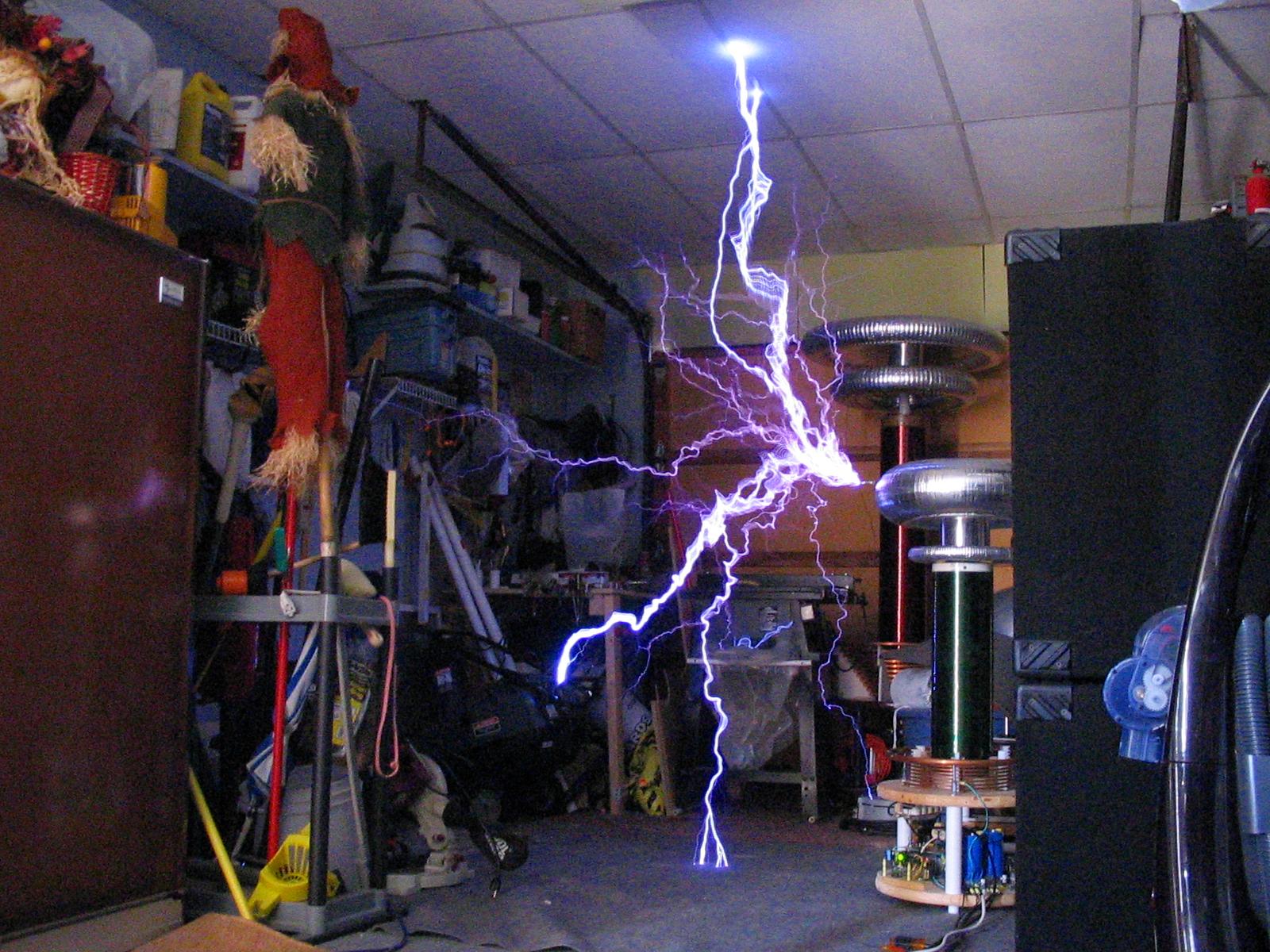
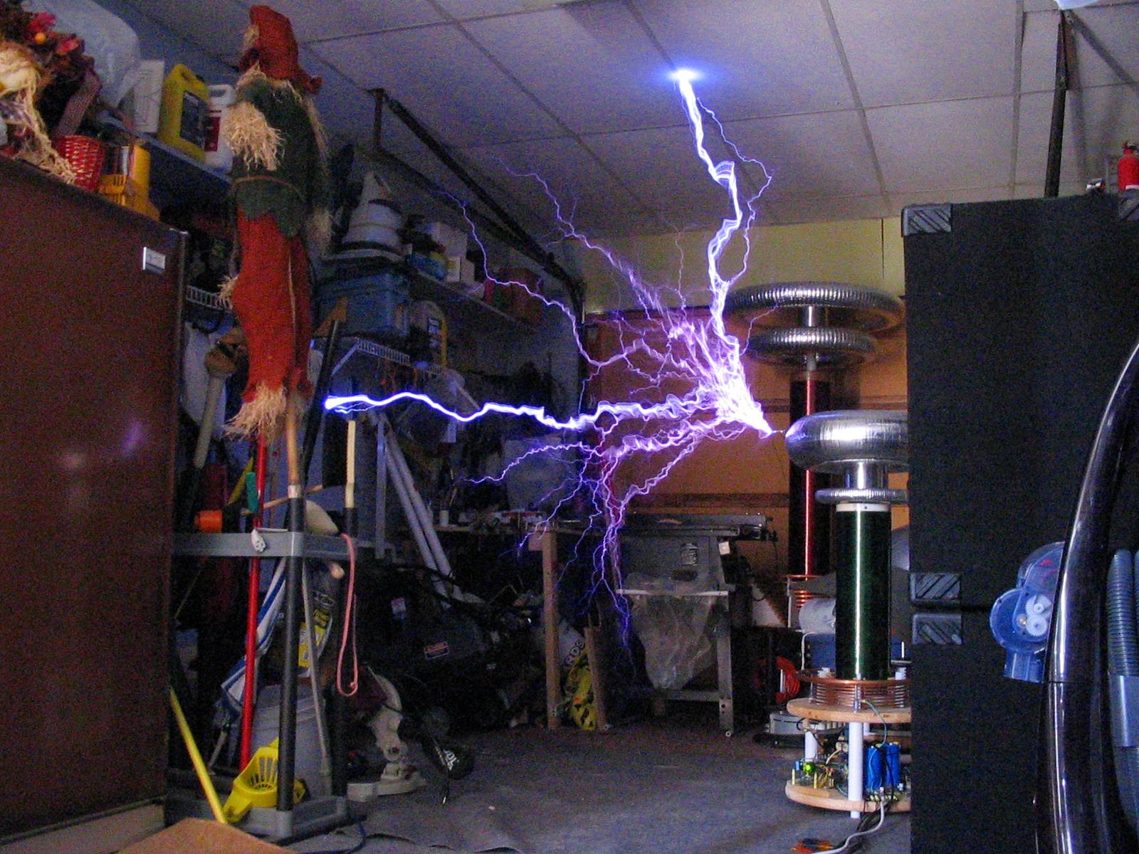
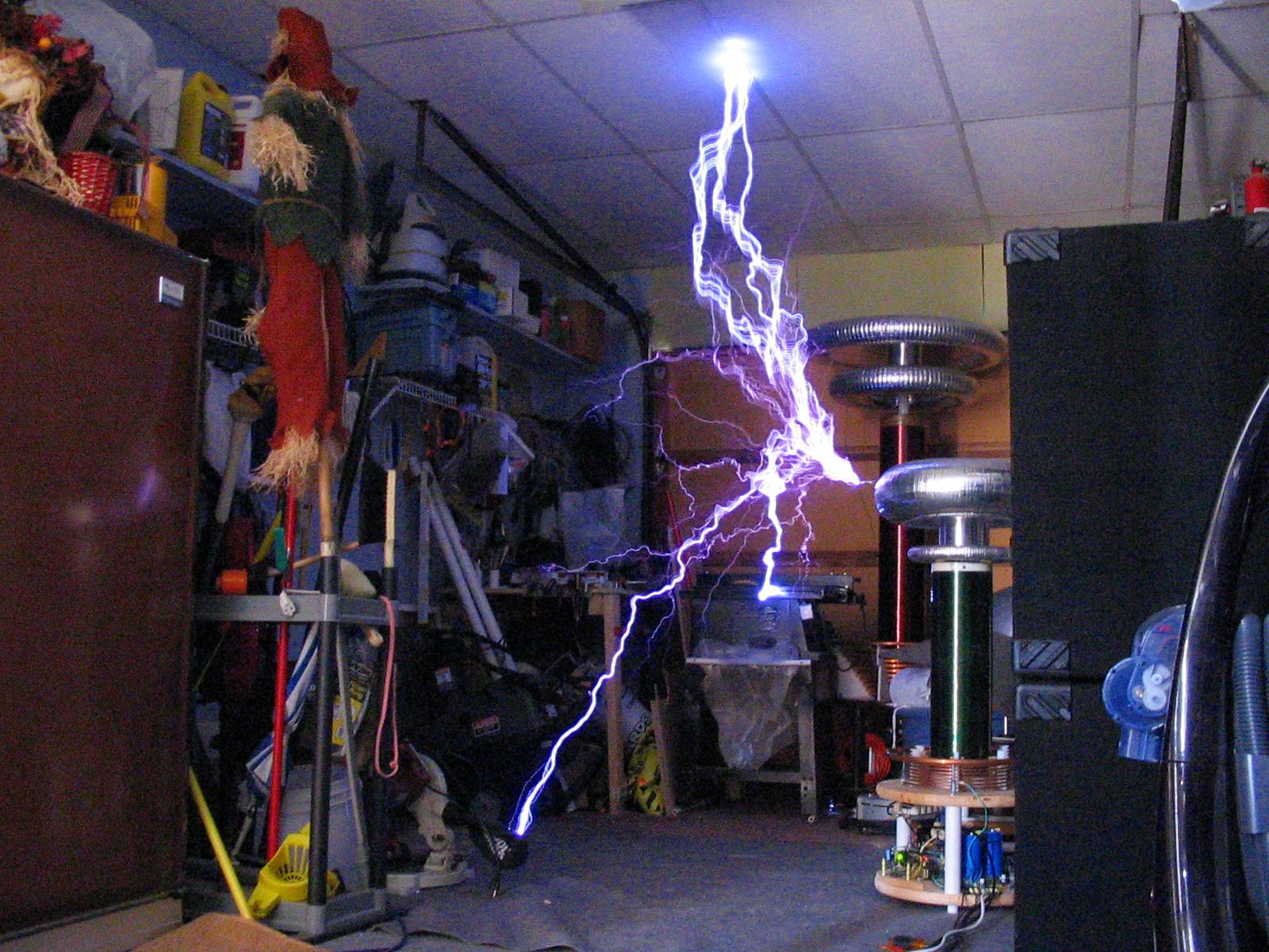
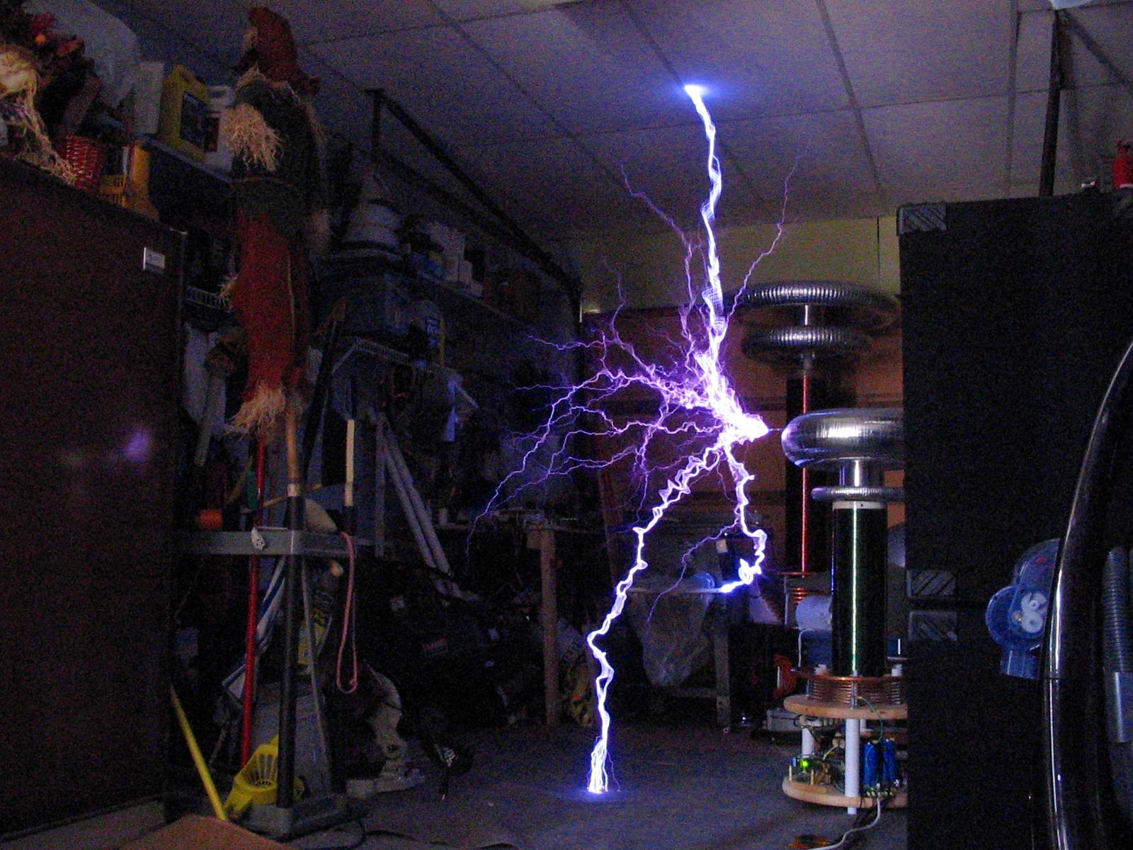
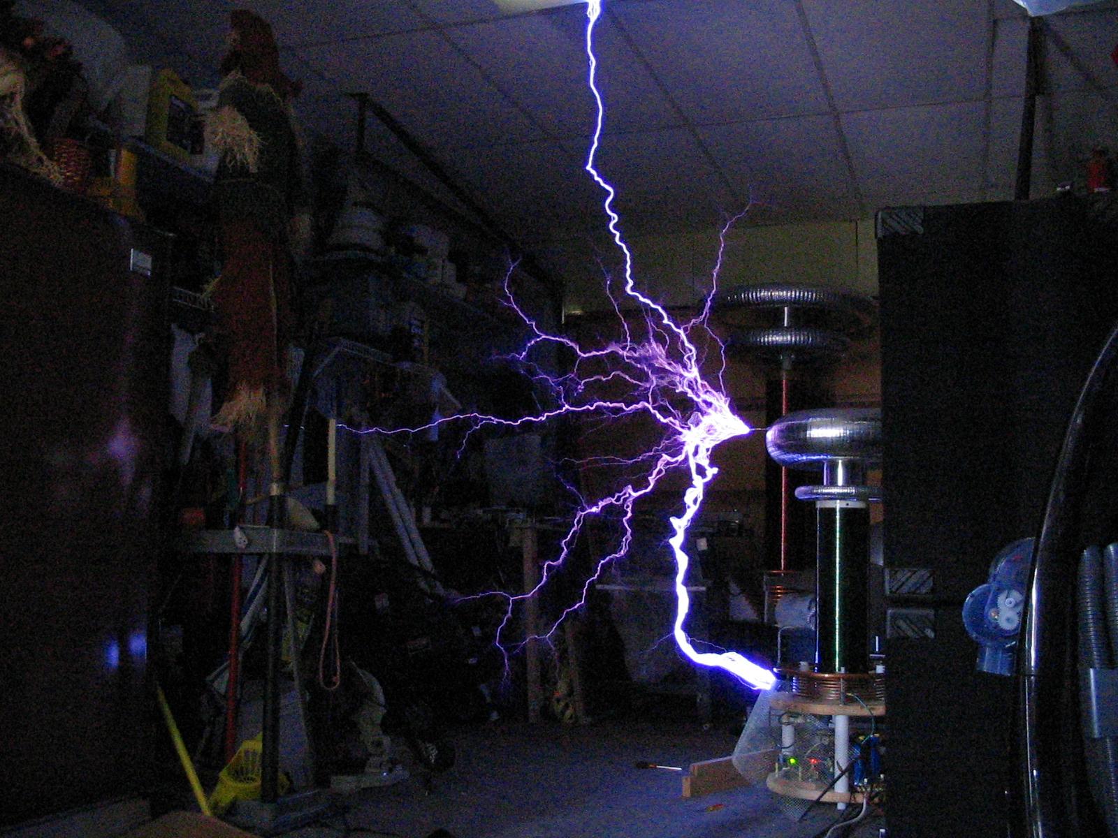
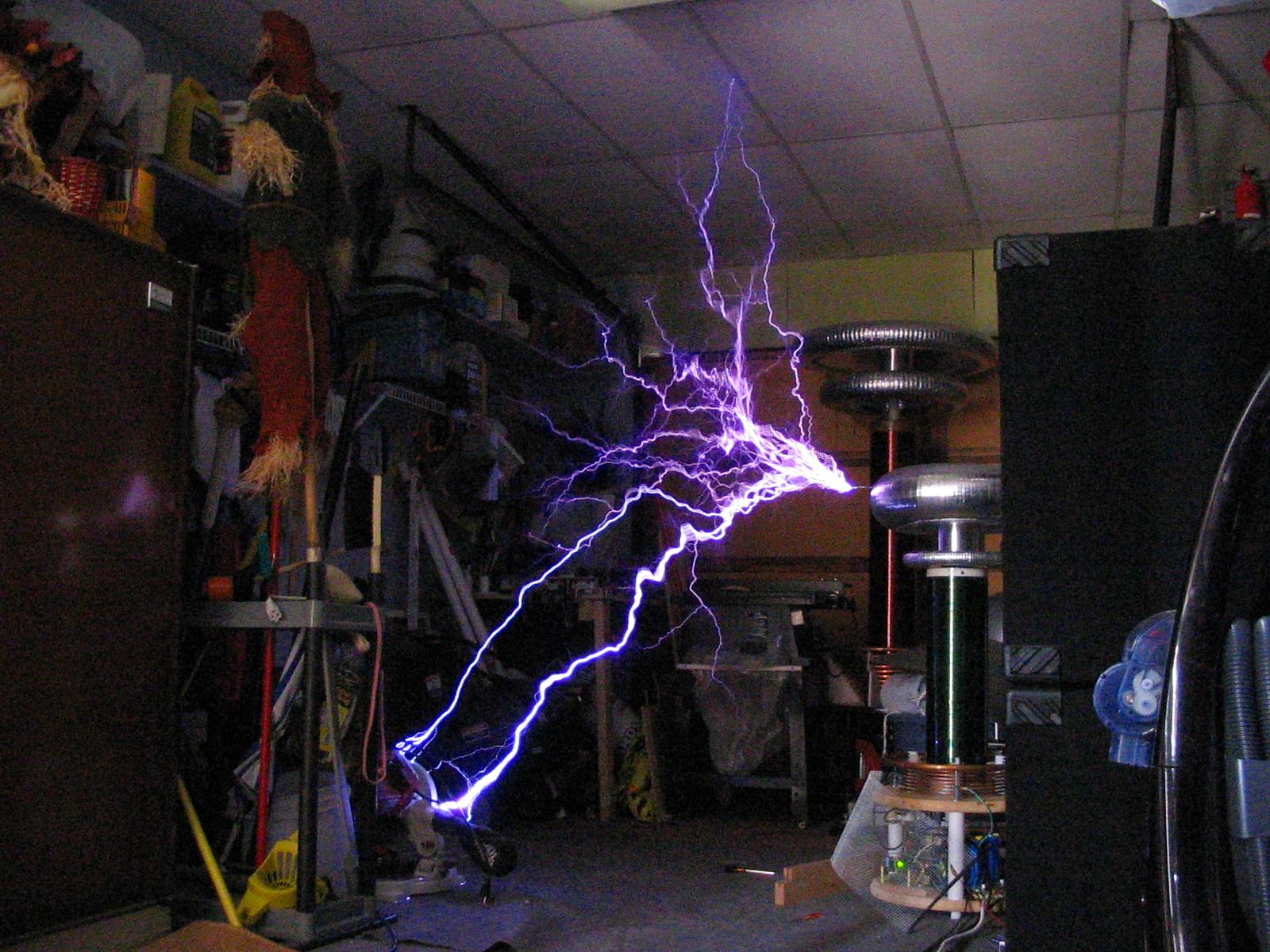
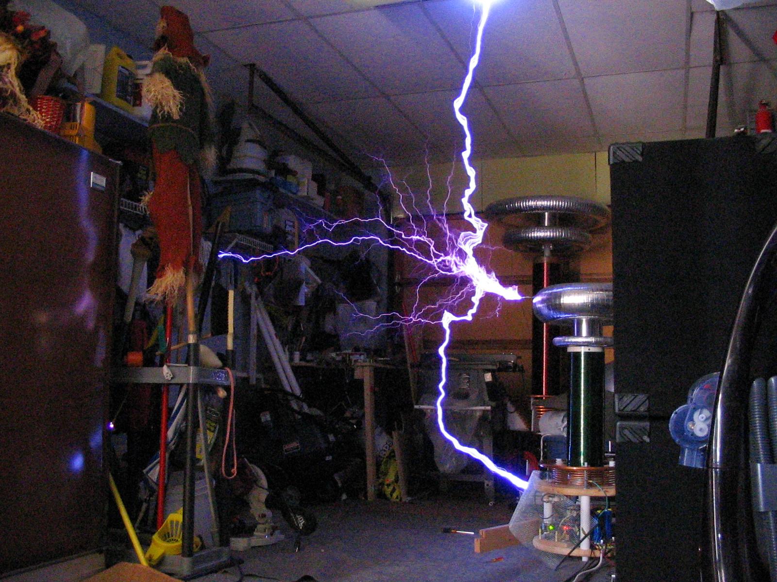
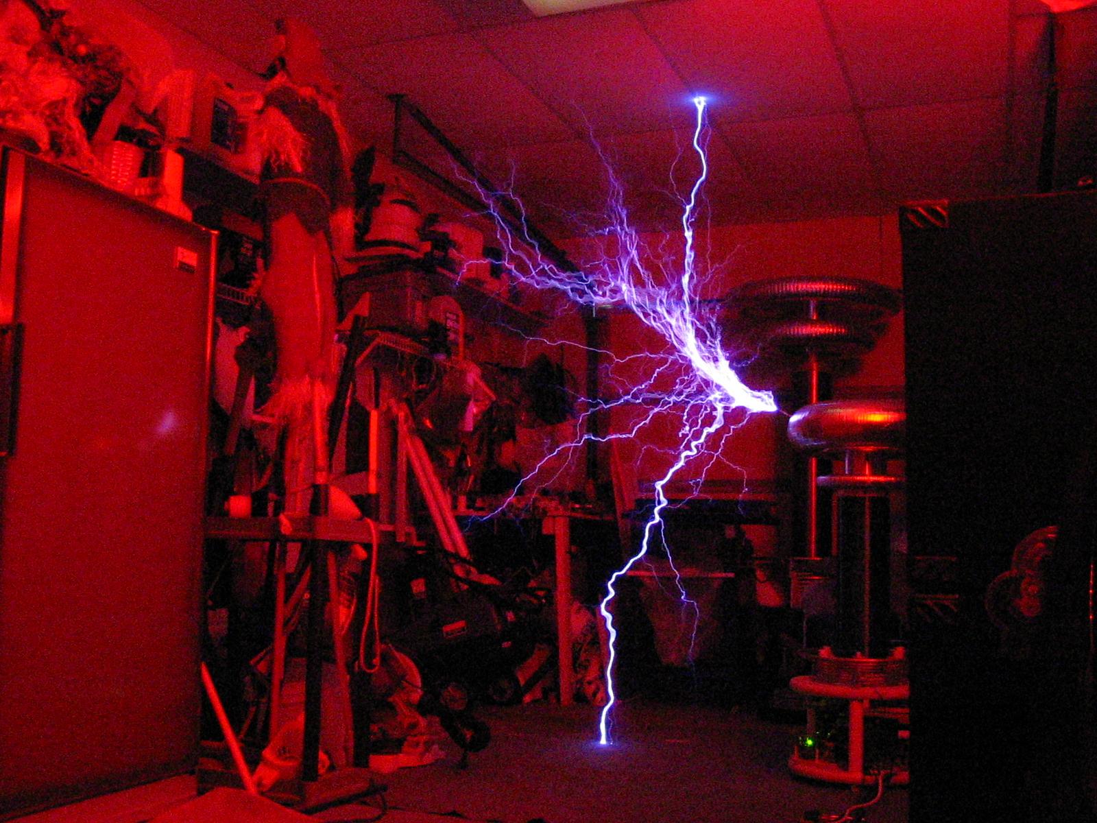
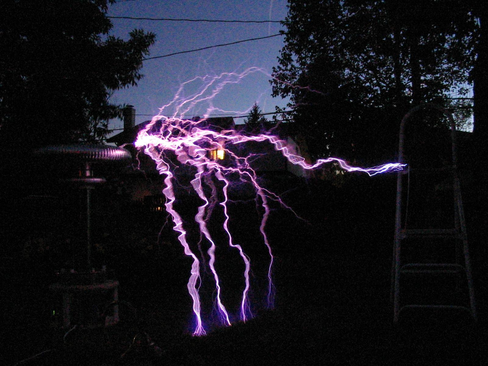
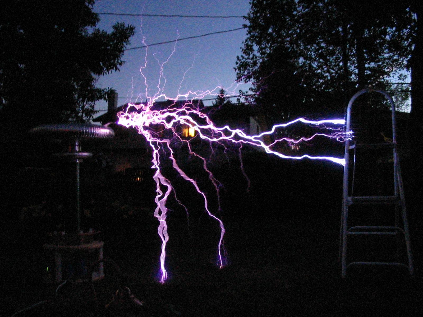
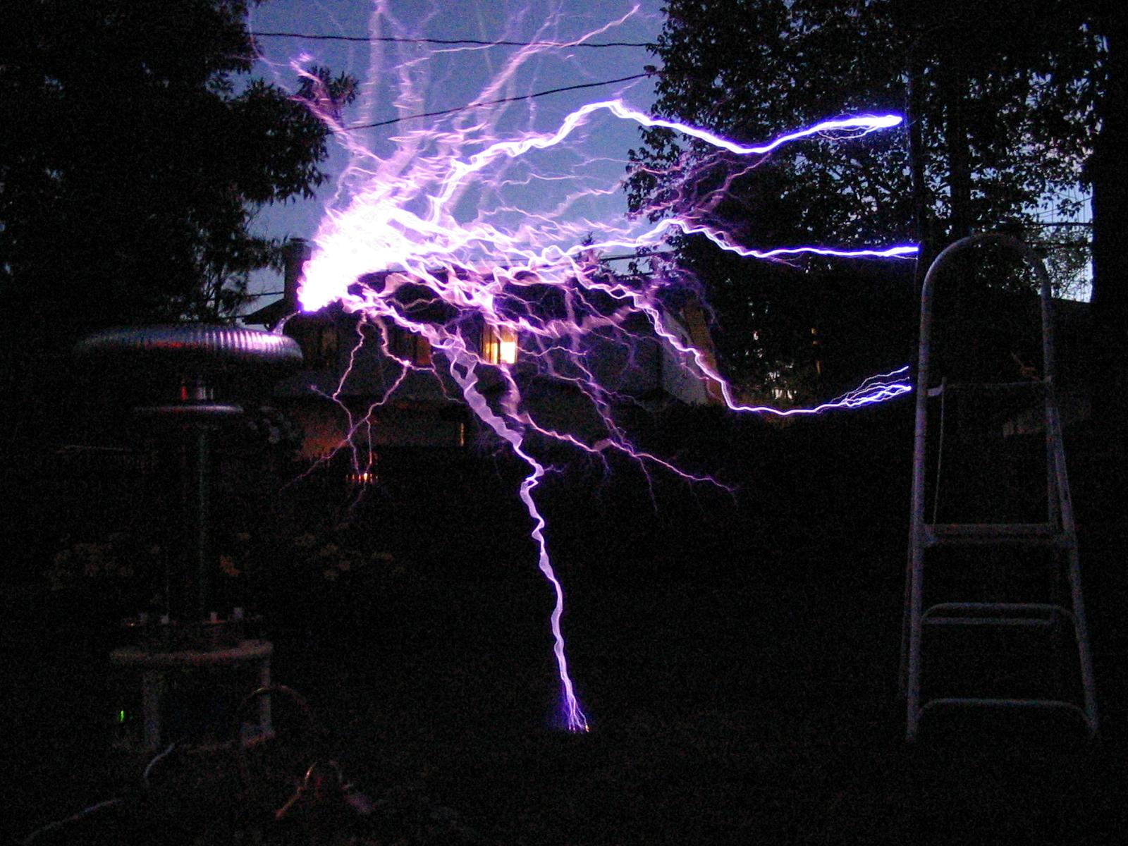
I did more tests tonight. One minor change was a larger toroid that only dropped the operating frequency a few % at most (the primary is tuned with 13uH at 5.5 turns). I started out running 9 cycles. I achieved 72" as usual. Then I reduced to 8 cycles, then 7, then 6, and I still managed 72"! But there was a lack of real intensity when running 6 cycles. 5 cycles only seemed to give about 5' sparks. The primary current was sitting at about 700A with air streamers and would occasionally trip the 800A limiter during heavier ground strikes. I ran the coil with 280VAC input (full-wave rectified input, no longer voltage doubler). The MMC only got slightly warm with 6 cycle operation :-). With 9 cycles the MMC gets uncomfortably hot to touch. It seems 6 cycles is the sweet spot for this setup, I am quite happy with 72" sparks from the 22" long secondary coil.
Below are a few 6' strikes:

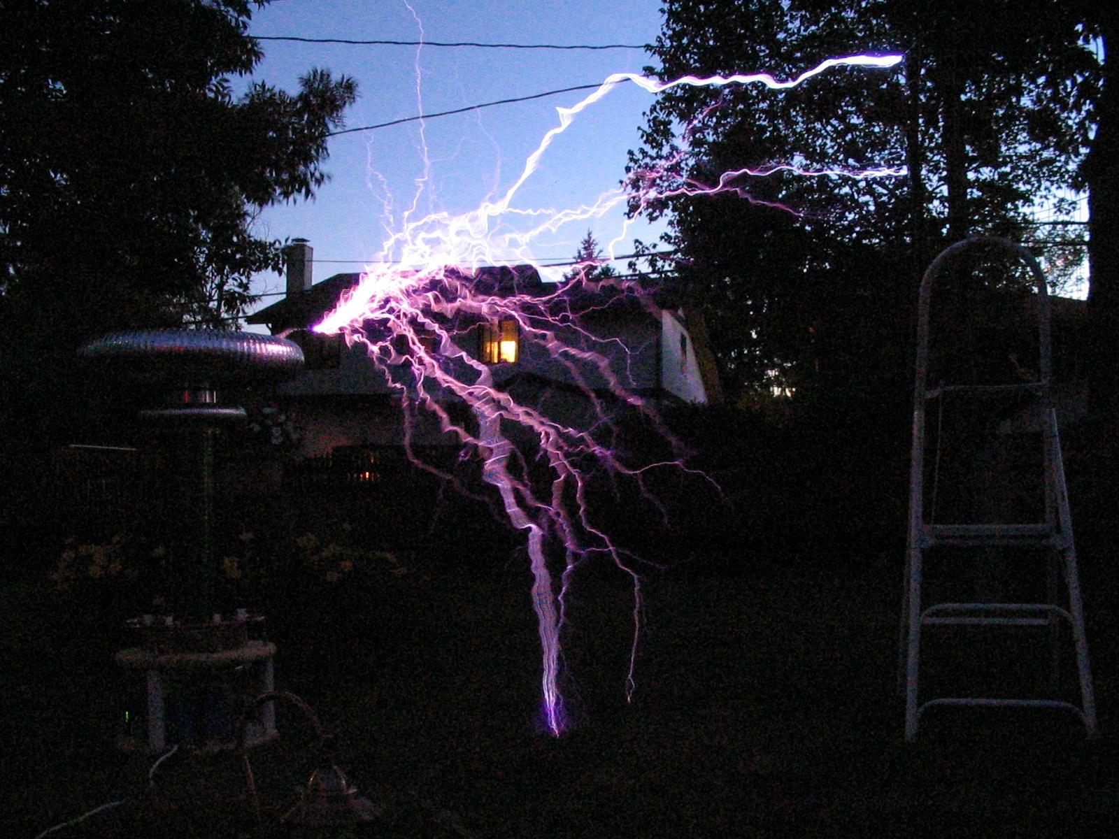
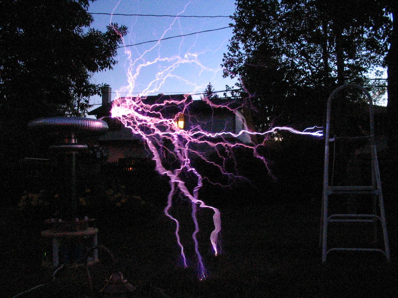
I then moved the target in to about 68" to get more repeatable strikes:
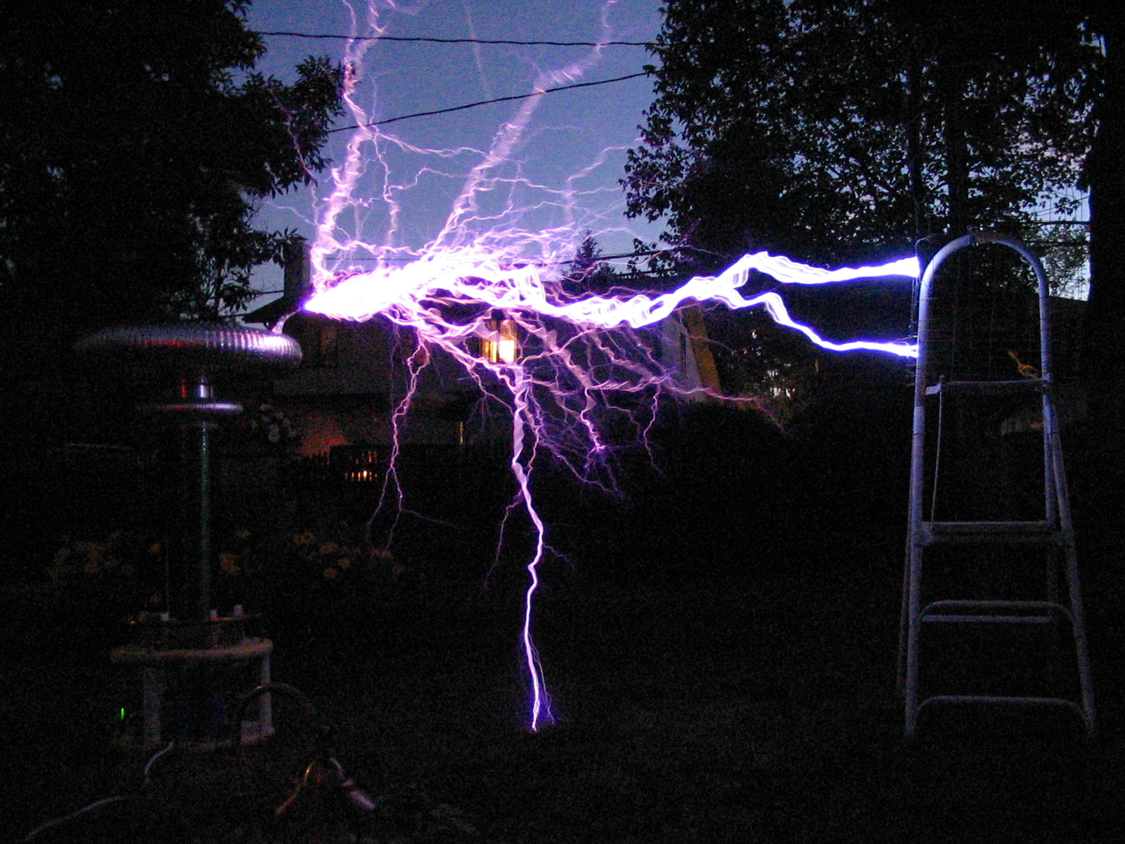
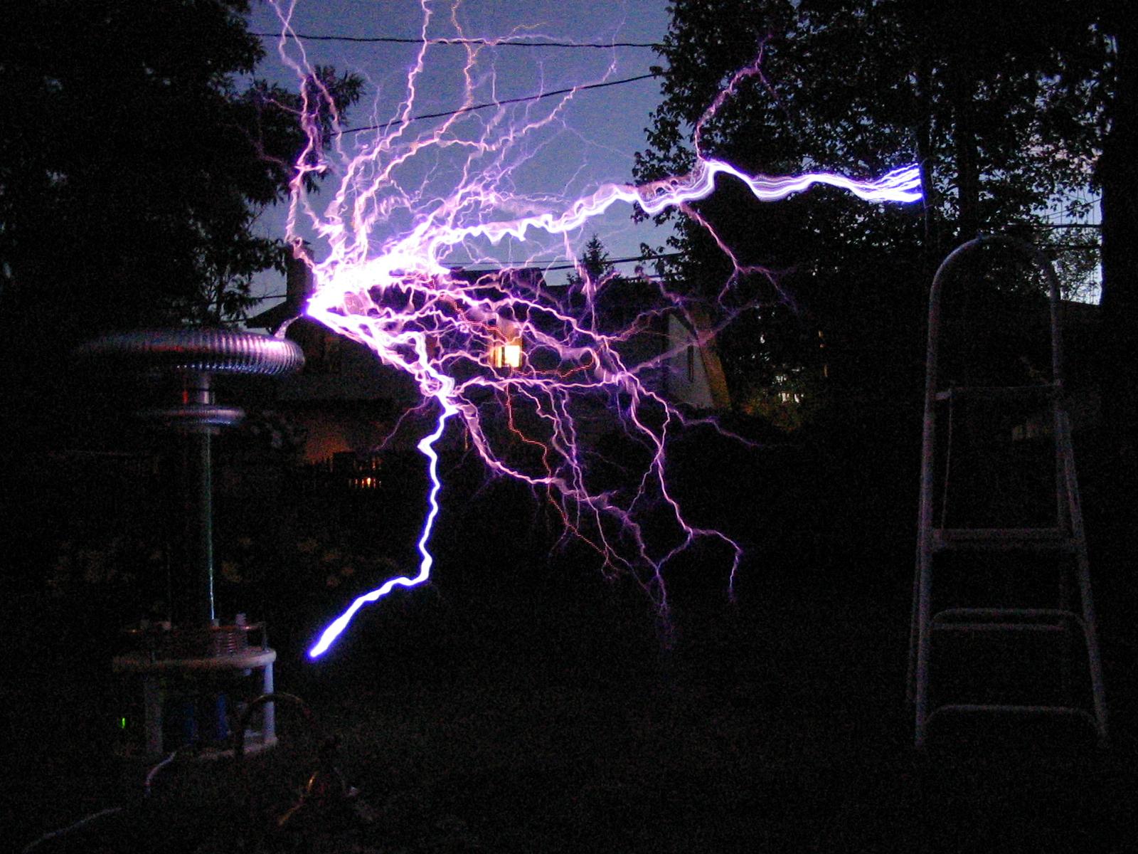
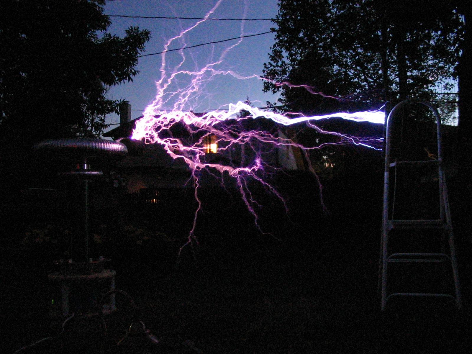
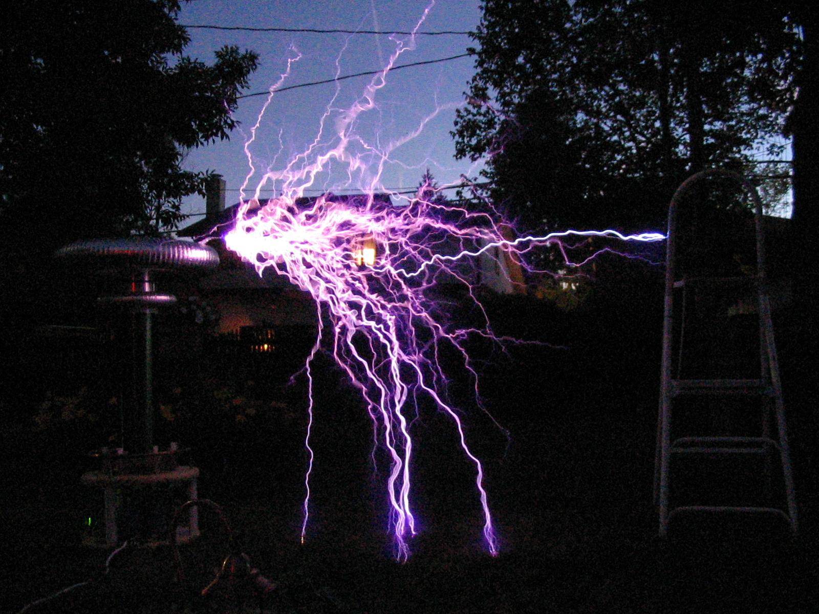
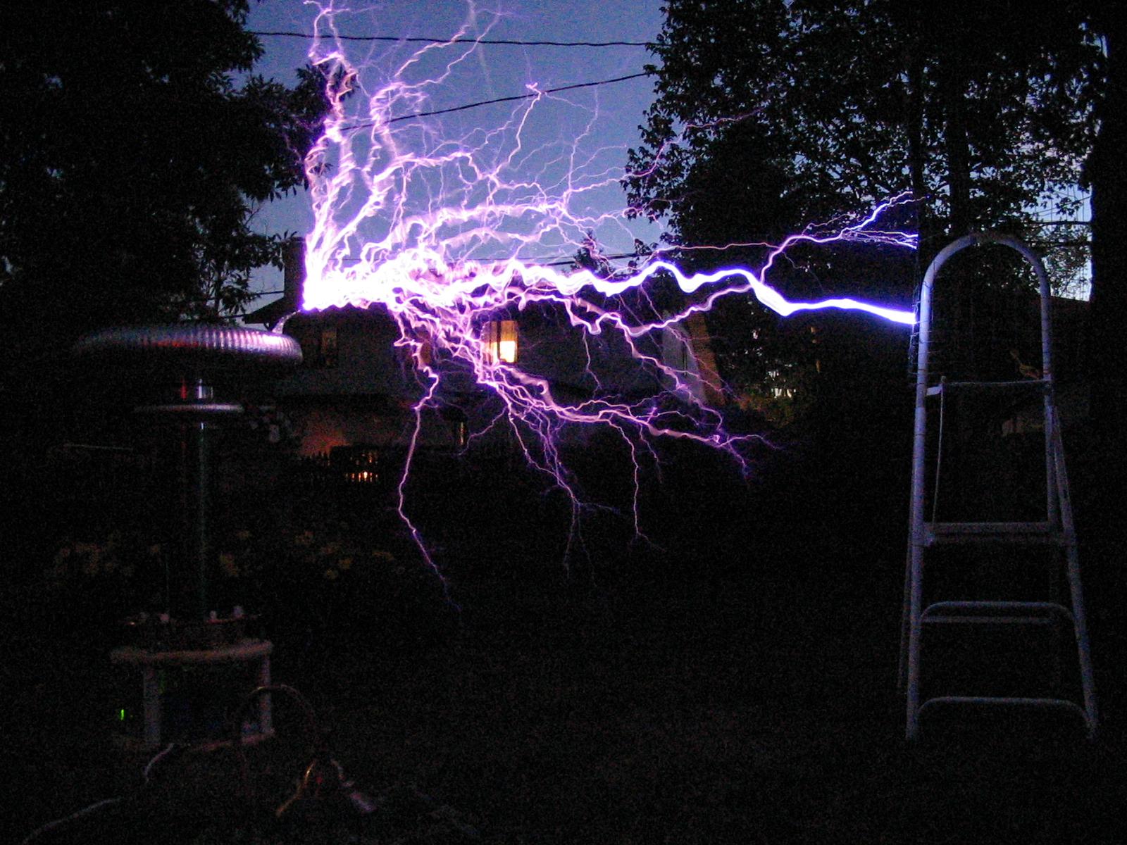
Note that the strikes to the ground were on average 65" or so.
Here is a VIDEO of this run (3.10MB .AVI)
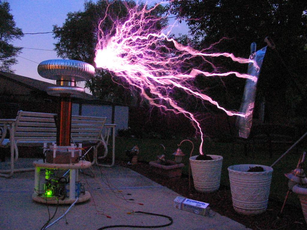
6/19/05:
Did a few more tests tonight. The coil sits innocently in the back yard:

Current specs (as shown in the above picture):
Lsecondary: 130mH
Csecondary: 45pF
Lprimary: 15.3uH
Cprimary: 450nF
Coupling: .19
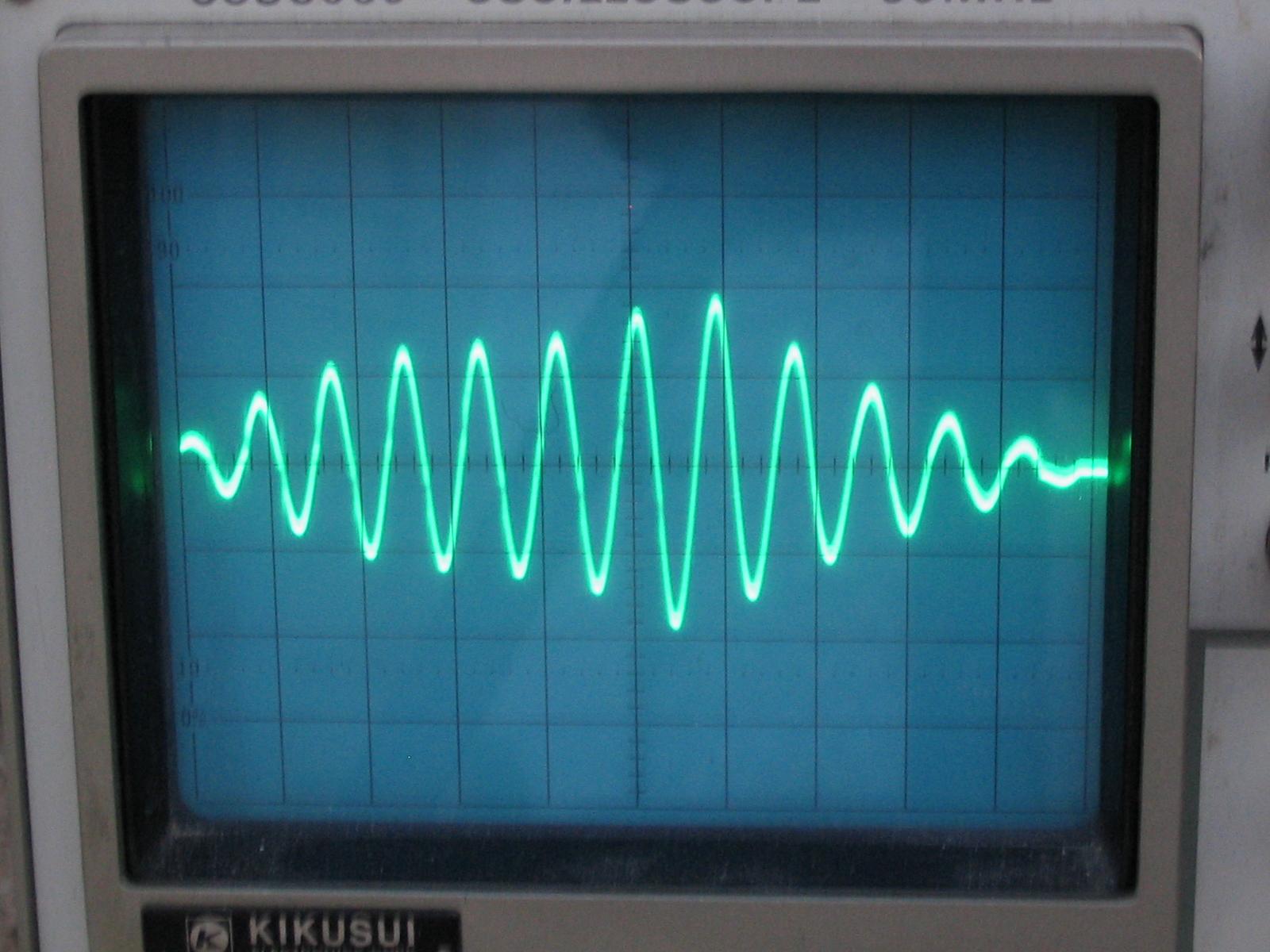
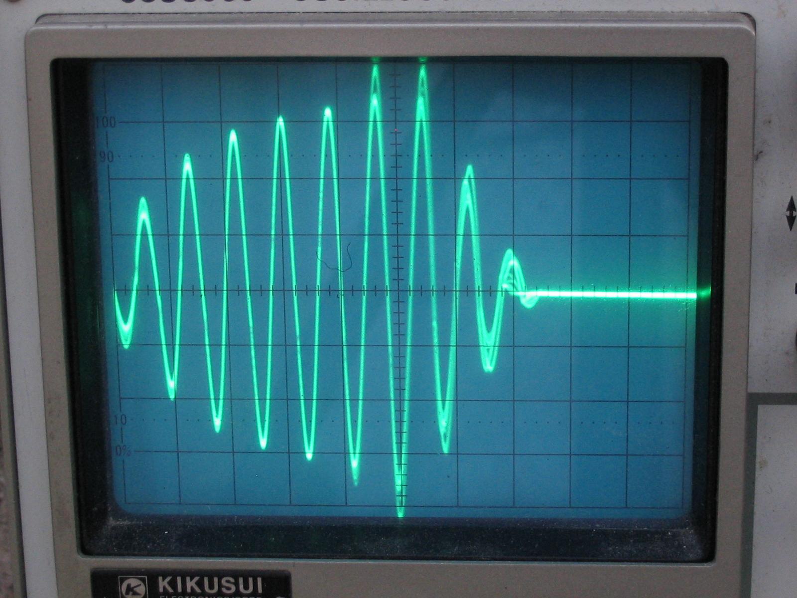
Anyway, I took some pictures of the scope as the coil was operating. The scope is set for 200A/div and a time base of 20uS/div.
 No
breakout yet, notice how the current grows some, settles, then grows a bit more
before its turned off at 118uS.
No
breakout yet, notice how the current grows some, settles, then grows a bit more
before its turned off at 118uS.
 A
bit of corona at the breakout point. Nearly 45% input voltage.
A
bit of corona at the breakout point. Nearly 45% input voltage.
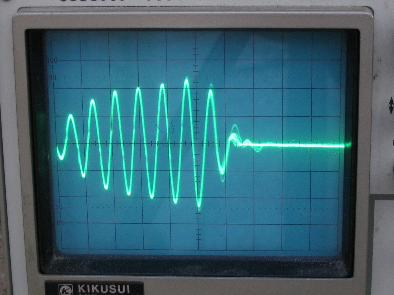 Finally
some 2-3 foot sparks. Note, i had to switch the trigger slope to get a
stable trigger (the number of cycles is still the same). The drive is shut
off at 105uS on the screen. Notice it only rings for 1 cycle afterward!
Finally
some 2-3 foot sparks. Note, i had to switch the trigger slope to get a
stable trigger (the number of cycles is still the same). The drive is shut
off at 105uS on the screen. Notice it only rings for 1 cycle afterward!
 Longer
streamers, about 5 feet. Current nearing 700A pk or so. Interesting
that the ringdown at the end is not quite so fast... maybe I need more tuning?
Longer
streamers, about 5 feet. Current nearing 700A pk or so. Interesting
that the ringdown at the end is not quite so fast... maybe I need more tuning?
 Finally,
a heavy arc to a grounded object. Arc connects at 90uS or so on the scope
screen, current hits 800A (just under the limiters threshold).
Finally,
a heavy arc to a grounded object. Arc connects at 90uS or so on the scope
screen, current hits 800A (just under the limiters threshold).
Hopefully these pictures will aid in the development of the DRSSTC model.
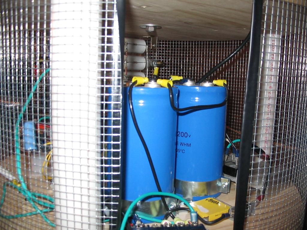
UPDATE 12/15/05:
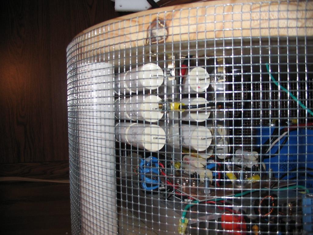
Today I decided to do a bit of work on this project, mainly just drilling a center hole in my new 24x6" spun toroid. I also added an electrostatic shield around the electronics (in the form of 1/4" mesh). This should keep everything relatively safe from streamers.
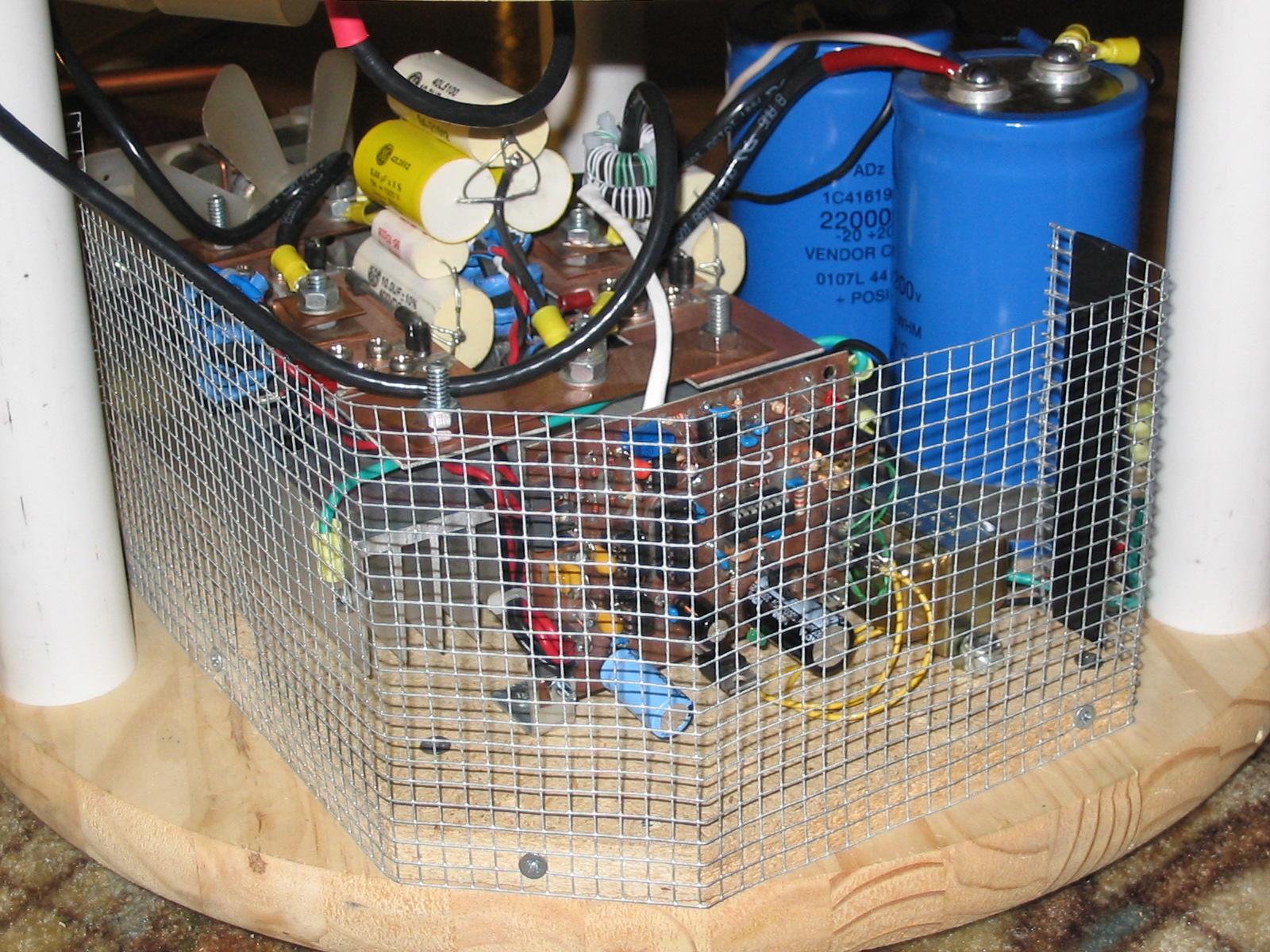
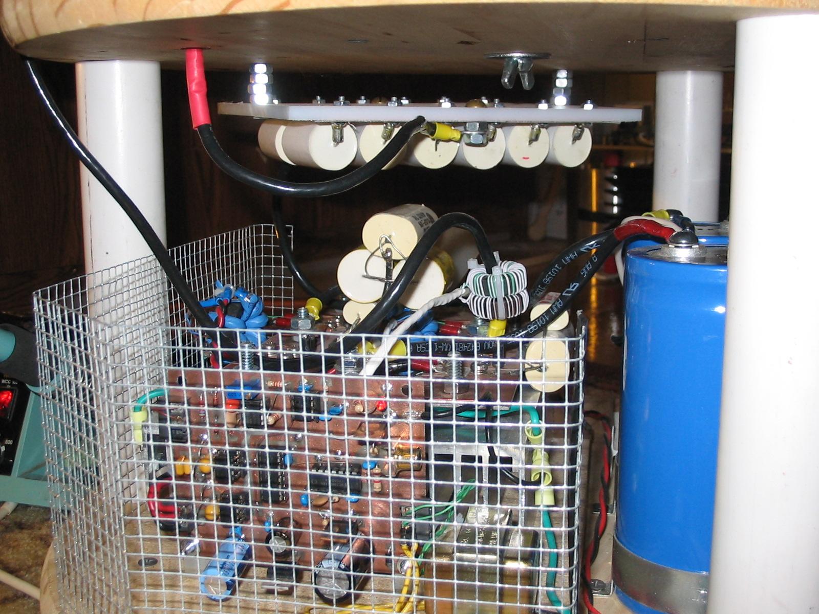
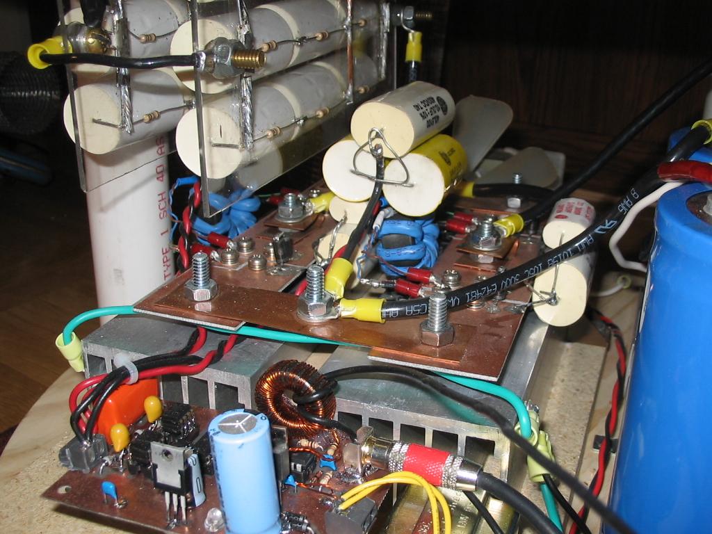
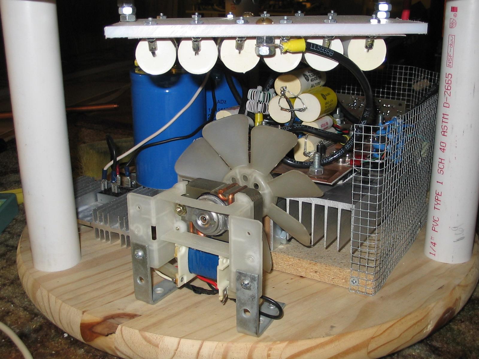 Various shots of the electronics.
 Here you can see the second set of CTs hidden behind the circuit board.
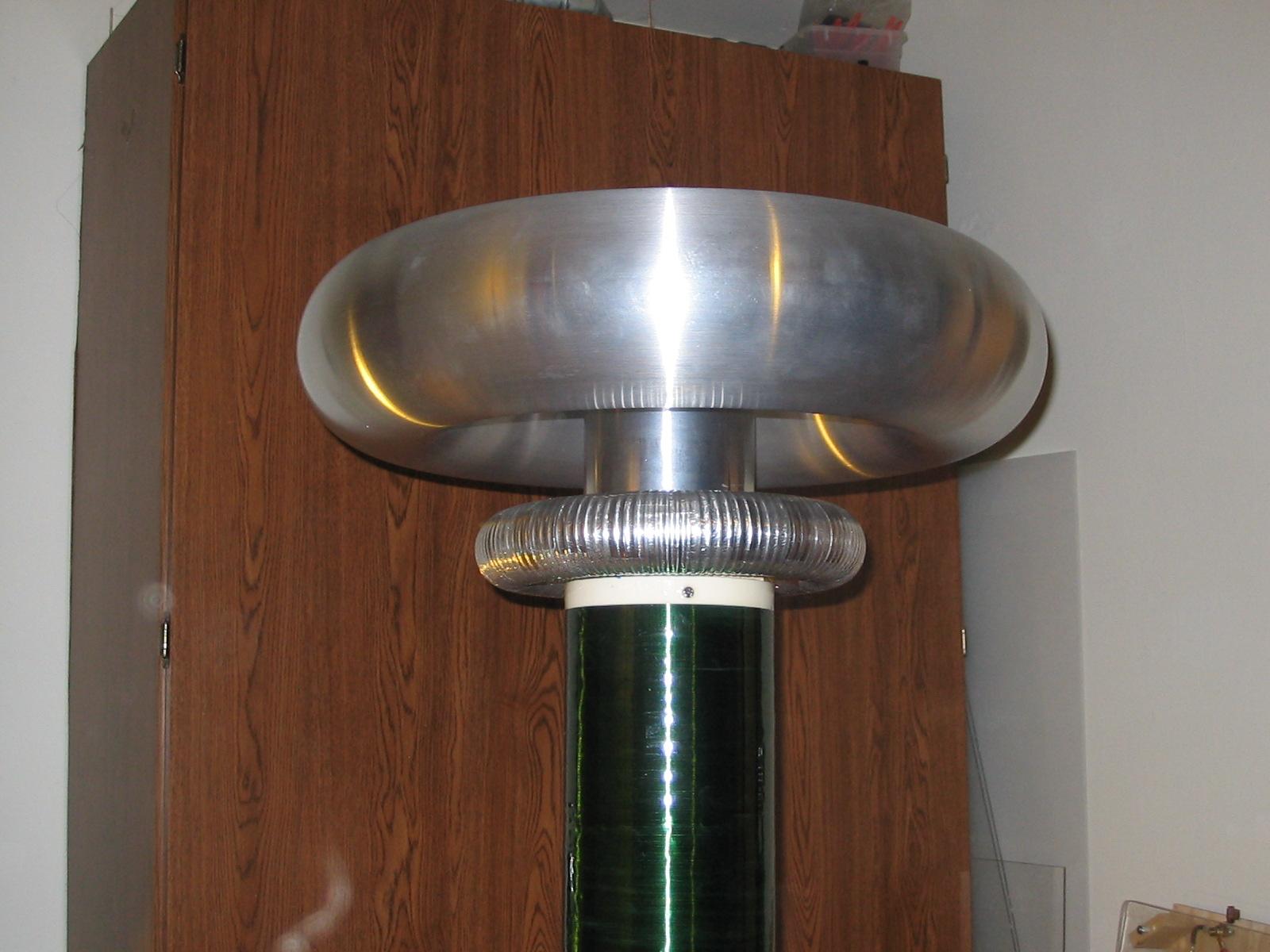 The wonderful spun toroid.
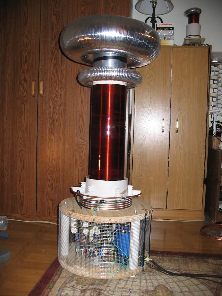
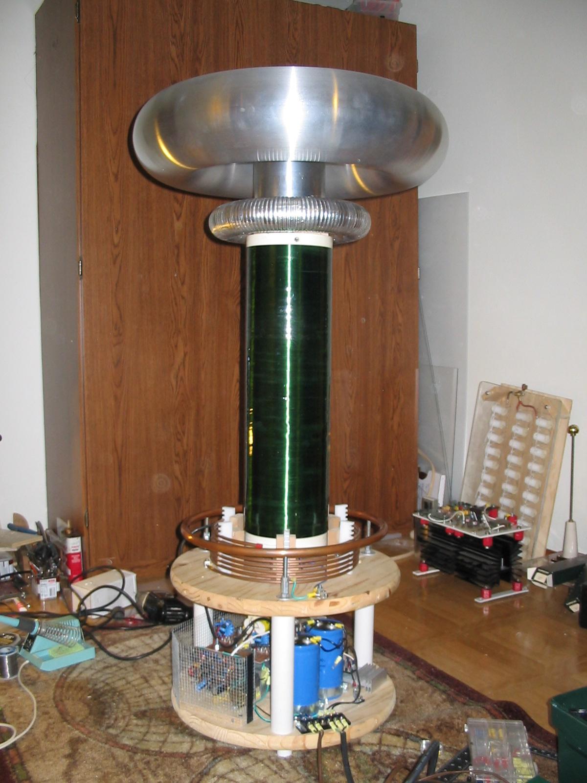 The whole coil. The spun toroid really sets it off.